Moog Animatics SmartMotor™ Developer's Guide,Rev. L
Page 888 of 909
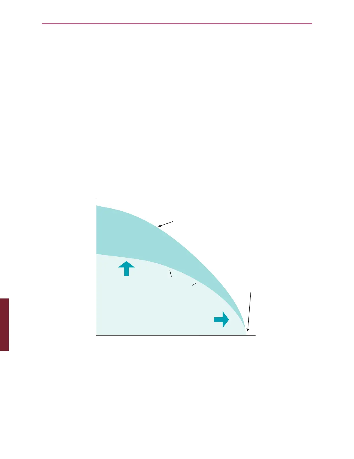
Torque Curves
Understanding Torque Curves
Each set of torque curves depicts the limits of both continuous and peak torque for a given
SmartMotor™ over the full range of speed.
Peak Torque
The peak torque curve is derived from dyno (dynamometer) testing. It is the point at which
peak current limit hardware settings of the drive prevent further torque in an effort to protect
the drive-stage components.
Continuous Torque
The continuous torque curve is also derived from dyno testing. It is the point at which the
temperature rises from an ambient of 25ºC to the designed thermal limit.
For example, the motor will be placed on the dyno tester and set to operate at 1000 RPM
continuously with the load slowly increased until the controller reaches its maximum
sustained thermal limit. This limit is either 70ºC or 85ºC depending on the model number. All
Class 5 SmartMotor servos are set to 85ºC.
Peak Torque Curve
(fit to curve)
No-Load
Maximum Speed
Voltage Limited
Speed (RPM)
Motor Torque
Continuous Torque Range
Thermally Limited
Peak Torque Range
Continuous
Torque Curve
(fit to curve)
Torque Curve
The lower-right side of the curve is limited by supply voltage. This is the point at which Back
EMF suppresses any further speed increase. Higher supply voltages will shift the zero torque
point of the curve further to the right.
Appendix: Torque Curves