14 1 ENGINE SYSTEMS
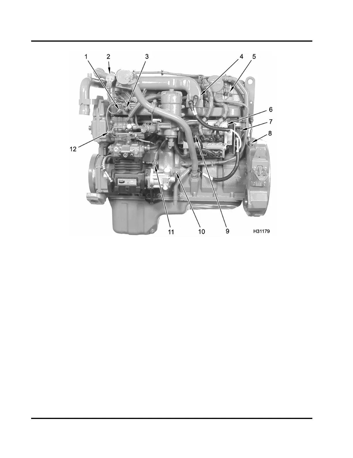
Figure 5 Component location, electrical– left
1. Manifold Absolute Pressure
(MAP) se nsor
2. EGR control valve
3. Manifold Air Temperature (MAT)
sensor
4. Inlet Air Heater (IAH) assembly
5. Valve cover gasket pass-through
connector
a. (Six) four wire connectors
for fuel injectors
b. (One ) three wire connector
for ICP sensor
c. Engine brake application –
(one) three wire connector
for t he BCP sensor and
(one) three wire connector
for the brake shut-off valve.
6. ECM and IDM module assembly
7. IAH relay
8. Crankshaft Position (CKP)
sensor
9. EGR drive module
10. Ground stud
11. Engine Oil Pressure (EOP)
sensor
12. Engine Oil Temperature (EOT)
sensor
EGES-270-1
Read all safety instructions in the "Safety Information" section of this manual before doing any procedures.
Follow all warnings, cautions, and notes.
© August 2008 Navistar, Inc.
 Loading...


