1 ENGINE SYSTEMS 15
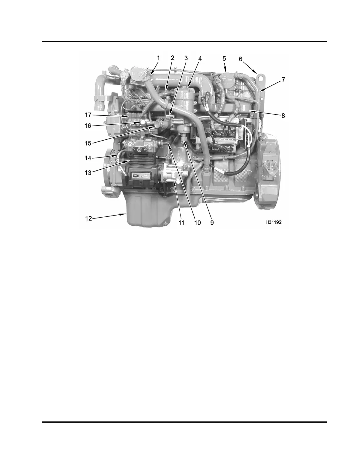
Figure 6 Component location, mechanical – left
1. Oil level gauge tube
2. High-pressure oil hose
3. Water drain valve (fuel)
4. Fuel filter header assembly
5. Breather assembly
6. Lifting eye
7. Vent and drain tube assembly
8. Intake manifold
9. Drain valve (fuel strainer)
10. Coolant hose (supply)
11. Power steering pump
12. Oil pan assembly
13. Air compressor
14. Oil supply line
15. Fuel primer pump assembly
16. Low-pressure fuel supp ly pump
17. High-pressure oil pump
assembly
EGES-270-1
Read all safety instructions in the "Safety Information" section of this manual before doing any procedures.
Follow all warnings, cautions, and notes.
© August 2008 Navistar, Inc.
 Loading...


