-xxi-
Figures
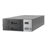
Figure 1-1 Front of the Library (Above: T30A/Below: T60A) ......................................................... 2
Figure 1-2 Operator panel ............................................................................................................. 3
Figure 1-3 Magazine operation panel(left:T30A,right:T60A) .......................................................... 5
Figure 1-4 Slot Number of Magazine(Above:T30A,Below:T60A) ................................................... 7
Figure 1-5 Components on the Rear of the Library(T30A) .............................................................. 9
Figure 1-6 Components on the Rear of the Library(T60A) .............................................................. 9
Figure 1-7 Components of Rack mount kit parts ........................................................................... 16
Figure 1-8 Illustration of Rack Bars ............................................................................................ 17
Figure 1-9 Rack Dimensions ....................................................................................................... 18
Figure 1-10 Rack mount rail attachment position.......................................................................... 19
Figure 1-11 attachment of rack mount rails .................................................................................. 20
Figure 1-12 attachment of rack mount bracket R(left:T30A , right :T60A) ...................................... 21
Figure 1-13 attachment of rack mount bracket L(left:T30A , right :T60A) ...................................... 21
Figure 1-14 Mounting of library onto rack ................................................................................... 22
Figure 1-15 attachment of rack ears ............................................................................................. 23
Figure 1-16 Fastening of Library’s front side ............................................................................... 24
Figure 1-17 attachment of label plate ........................................................................................... 25
Figure 4-1 Menu Screen ............................................................................................................. 32
Figure 4-2 Component of Operator Panel ..................................................................................... 33
Figure 4-3 Accessor Icon ............................................................................................................ 34
Figure 4-4 Magazine Icon ........................................................................................................... 35
Figure 4-5 Magazine Icon(Magazine is Opened) .......................................................................... 35
Figure 4-6 Magazine Icon(I/O Station is set) ................................................................................ 35
Figure 4-7 Magazine Icon (I/O Station is opened) ........................................................................ 36
Figure 4-8 Magazine Icon(Slot Image) ........................................................................................ 36
Figure 4-9 Root screen of Top Menu ........................................................................................... 46
Figure 4-10 Move Cartidge ......................................................................................................... 69
Figure 4-11 Select source Screen................................................................................................. 69
Figure 4-12 Select Destination Screen ......................................................................................... 70
Figure 4-13 Select Execute ......................................................................................................... 70
Figure 4-14 Move Cartridge ....................................................................................................... 71
Figure 4-15 Select source screen ................................................................................................. 71
Figure 4-16 Select Destination screen .......................................................................................... 72
Figure 4-17 Select Execute ......................................................................................................... 72
Figure 4-18 Reboot Library ........................................................................................................ 74
Figure 5-1 Input URL................................................................................................................. 78
Figure 5-2 Login page(before entry) ............................................................................................ 83
Figure 5-3 Login page(after entry) .............................................................................................. 83
Figure 5-4 Library Basic Information Window ............................................................................. 84
Figure 5-5 Library map .............................................................................................................. 86
Figure 5-6 Detail(Magazine) ....................................................................................................... 87
Figure 5-7 Accessor Information ................................................................................................. 88
Figure 5-8 Library information ................................................................................................... 89
Figure 5-9 Network information.................................................................................................. 90
Figure 5-10 Notification information ........................................................................................... 91
Figure 5-11 Drive information .................................................................................................... 92
Figure 5-12 Move Cartridge ....................................................................................................... 93
Figure 5-13 Unload Drive ........................................................................................................... 95
Figure 5-14 Clean Drive ............................................................................................................. 96
Figure 5-15 Library state ............................................................................................................ 97
Figure 5-16 confirmation screen.................................................................................................. 97
Figure 5-17 UserAccess ............................................................................................................. 98
Figure 5-18 Add a User .............................................................................................................. 99
Figure 5-19 Remove a User confirmation screen ........................................................................ 100
Figure 5-20 Physical ................................................................................................................ 101
Figure 5-21 Logcal .................................................................................................................. 102
Figure 5-22 Network setup ....................................................................................................... 105