SECTION 5
DISASSEMBLY AND ASSEMBLY
58
Replace DPCA Boards
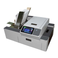
TO REMOVE INDIVIDUAL DPCA BOARDS:
1. Remove Exit Cover (4 screws).
2. Disconnect wire harnesses from
terminals on DPCA 1 [A] and/or
DPCA-2 [B].
NOTE: Wire harnesses are
labelled for easy reconnection.
DPCA-1 wire harnesses are
labelled (-1) and DPCA-2 wire
harnesses are labelled (-2).
3. Remove (4) mounting screws
securing DPCA-1 or DPCA-2 to
the DPCA Bracket. Remove the DPCA Board.
4. Reassemble in reverse order. NOTE: Be sure to carefully reconnect the wire harnesses to the correct
DPCA Board.
TO REMOVE DPCA/MULTIPLEX PCB ASSEMBLY:
1. Remove Exit Cover (4 screws).
2. Remove (2) screws and washer securing the DPCA Bracket to the Printer Base (access under Printer).
3. Carefully disconnect wire harnesses from the Multiplex PCB and DPCA-1 and DPCA-2. Remove
Assembly. NOTE: Wire harnesses are labelled for easy reconnection. DPCA-1 wire harnesses are
labelled (-1) and DPCA-2 wire harnesses are labelled (-2).
4. Reassemble in reverse order. NOTE: Be sure to carefully reconnect the wire harnesses to the correct
DPCA Board.
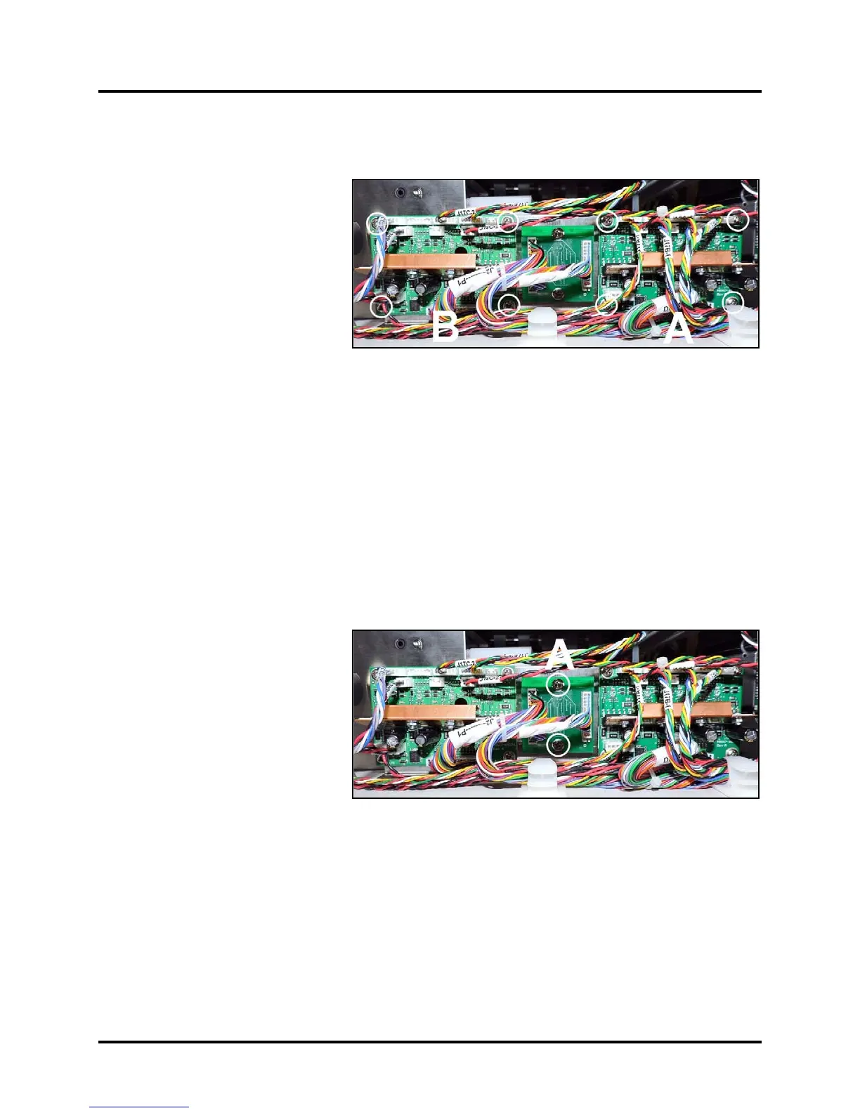
Replace Multiplex (MUX) Board
1. Remove Exit Cover (4 screws).
2. Disconnect wire harnesses from
terminals on Multiplex PCB [A].
NOTE: Wire harnesses are
labelled for easy reconnection.
3. Remove (2) mounting screws
securing MX Board to the
DPCA/Multiplex PCB Bracket.
Remove the Multiplex Board.
4. Reassemble in reverse order.
NOTE: Be sure to carefully reconnect the wire harnesses.
 Loading...


