SECTION 5
DISASSEMBLY AND ASSEMBLY
59
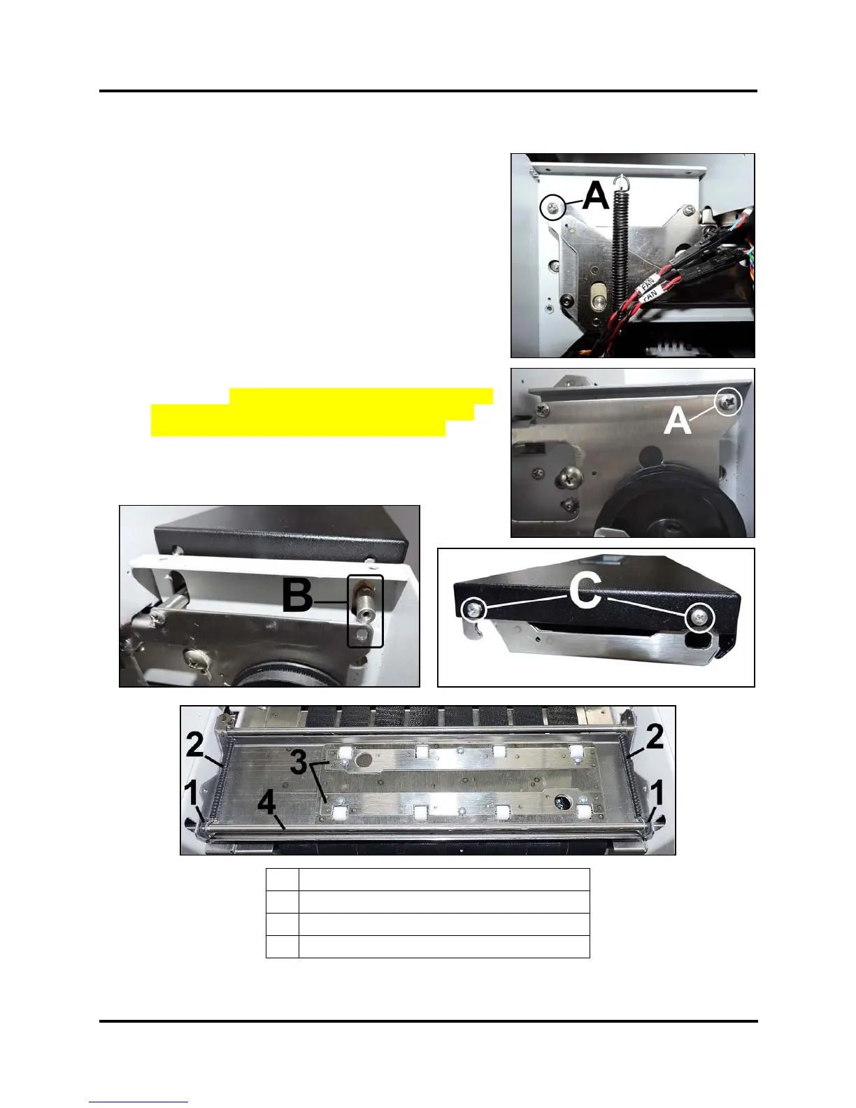
Replace Exit Cover and Exit Wheel Assembly
1. Before powering off the Printer, position the Media
Thickness adjustment to its lowest setting.
2. Remove Non-Operator Side Cover and Right-hand Operator
Side Cover.
3. Open Top Assembly and Exit Conveyor Cover.
4. Remove (2) screws securing the Exit Wheel Assembly [A]
(1 screw per side) to the Printer Side Frames.
5. Raise the rear of the Assembly up in the adjustment slots in
the Side Frame to access the mounting screws in the Cover.
6. Remove (4) screws securing Cover to the Exit Roller
Assembly [C] (2 screw per side). Remove the Cover. This
will provide access to the Exit Wheels Assembly
components. NOTE: You can also remove the Exit Wheel
Assembly at this point by maneuvering the ends of the
Support Rod through the slots in the Side Frame.
7. Reassemble in reverse order.
1.
E-Clips (x2)
2.
Exit Wheel Assembly Release Springs (x2)
3.
Exit Wheels and Springs
4.
Support Rod
 Loading...


