SECTION 5
DISASSEMBLY AND ASSEMBLY
77
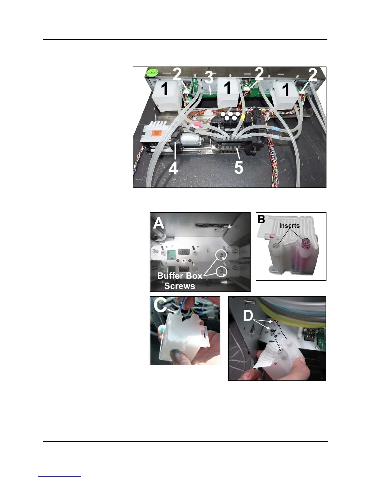
Ink Station Components
1. Buffer Boxes (x3)
2. QA Chip Assembly (x3)
3. Ink Tank Level PCA
4. Peristaltic Pump
(Waste Pump for Service
Station)
5. Dual Pinch Valve
Replace Buffer Boxes (3 per Printer)
1. Each Buffer Box is held in place
by (2) screws [A] accessed
through Ink Tank Station. Use a
long Phillips screwdriver,
remove screws and pull up on
box to remove it from Chassis.
2. Remove the old Tubing
Inserts (2) [B] from the used
Buffer Box (or from the ink
barbs if pulled loose from the
Buffer Box). Cut pieces of
tubing (TYGON AN80007 1/8"
ID x 1/4" OD, 1/16" thick wall
tubing) into 6.5-7mm (17/64"-
9/32") pieces to use as new
inserts. NOTE: Make sure
that the ends of the tubing are
cut square and that the edges
are smooth.
3. Install the inserts on the ink
needle nipples in the Ink Tank
Station (isopropyl alcohol works
as a good lubricant). Make sure the barb is flush with the end of
the tubing.
4. Apply alcohol on the inside of the ink inlet fitting [C] on the new
Buffer Box. Push the new Buffer Box down onto the Ink Tubing Inserts [D] installed previously until the
standoff posts are pressed firmly against the bulkhead.
5. Attach Buffer Box with (2) screws from inside Ink Tank Station.
 Loading...


