SECTION 5
DISASSEMBLY AND ASSEMBLY
93
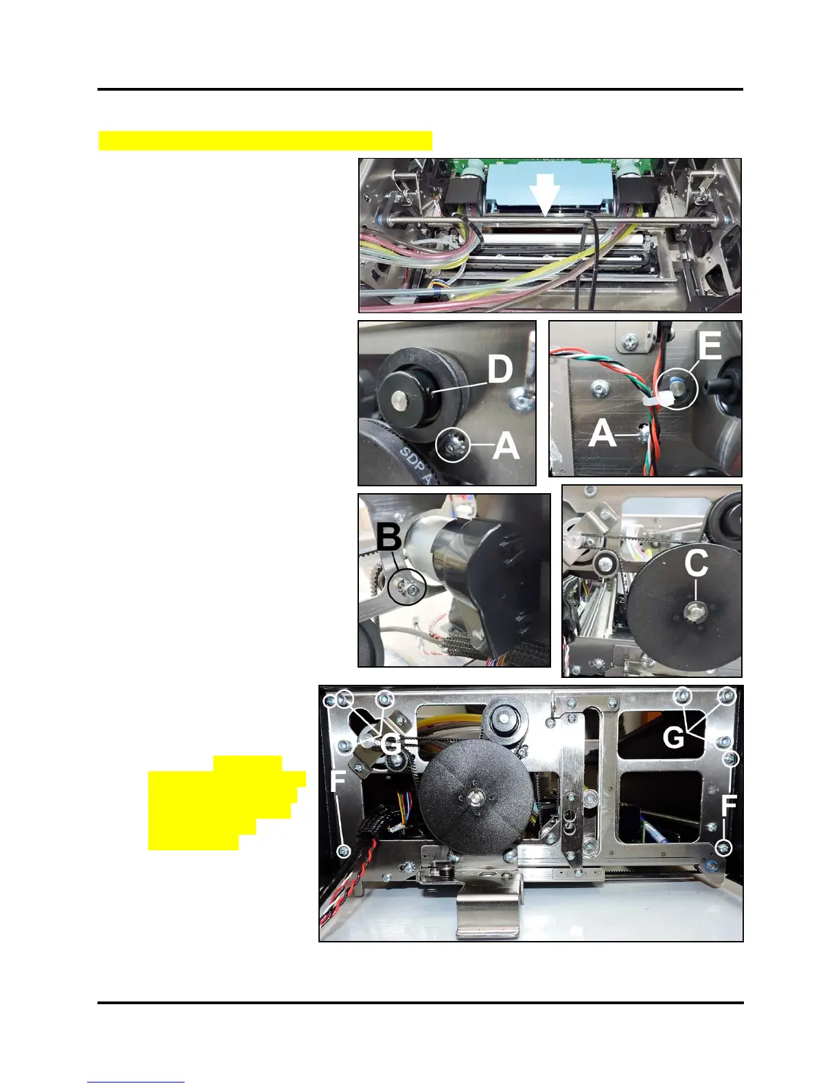
Remove Printhead Lifter Drive Shaft Assembly
1. Remove the Control Panel Cover.
2. Remove the Top Assembly
Rear Cover.
3. Loosen Tensioner Assembly screw
[A] (1 each side). This should
release the tension on the inner
Lifter Belts.
4. Operator Side.
Loosen Tensioner Assembly [B] for
Large Pulley belt. Remove the belt
from the Large Pulley. Remove the
E-clip securing the Large Pulley
[C] from the mounting stud.
Loosen set screw [D] securing the
Black Lifter Belt Pulley to the
Lifter Drive Shaft Assembly.
5. Non-operator Side. Remove the
E-clip [E] securing the Lifter Drive
Shaft Assembly.
6. Control Panel Side:
Remove (4) screws [F] securing the
Top Assembly Side Covers
(2 each side). Loosen (6) screws
[G] securing the Top Supports.
(3 screws per side.)
7. Pull the Side Frame away from the
Top Assembly enough to release
the Drive Shaft Assembly.
NOTE: You can also replace the
blue plastic bearings if necessary.
8. Install in reverse order:
NOTE: Install the Shaft
Assembly back through
the inner Lifter Belts and
the wire ties securing the
Ink Hoses. Tension the
Drive Belts, see Tensioning
the various Drive Belts in
the Adjustments Section.
System Test: Press
Printhead Test.
NOTE: Ink Hose wire tie
should be positioned with
the buckle facing down.
 Loading...


