SECTION 5
DISASSEMBLY AND ASSEMBLY
89
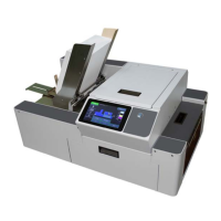
Remove Latch Release Assembly
1. Remove the Control Panel Cover.
2. Remove (2) screws [A] securing the
Latch Release Assembly to the Top
Assembly Frame.
3. Remove the Latch Release Assembly
from the Printer.
4. Install in reverse order.
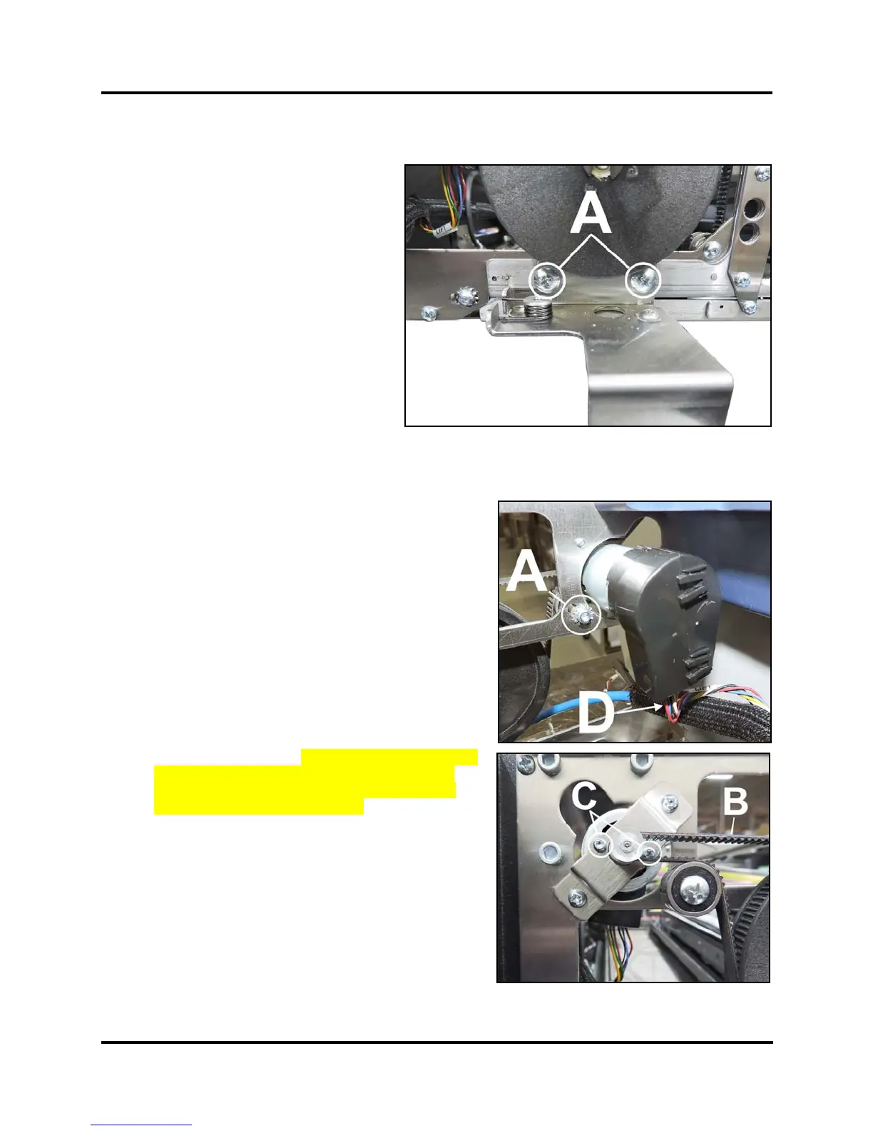
Remove Printhead Lift Motor Assembly and/or Drive Belt
1. Remove the Control Panel Cover. Disconnect the
Touchscreen Ethernet Cable if necessary. Carefully set
Control Panel Cover Assembly aside.
2. Loosen the Idler/Tensioner Assembly [A]. Slide
Assembly in slot to loosen the Drive Belt [B].
3. Remove the drive belt from the Printhead Lift Motor.
4. Remove (2) screws [C] securing Lift Motor to the Lift
Motor Bracket.
5. Turn Motor Assembly to disconnect the Lift Motor wire
harness [D].
6. Remove the Printhead Lift Motor Assembly through the
Top Assembly Frame.
7. Install in reverse order. NOTE: Check/adjust tension
on the Belt. See “Printhead Lift Motor Drive Belt
Tension Adjustment” in the Adjustments Section.
System Test: Press Printhead Test.
 Loading...


