SECTION 5
DISASSEMBLY AND ASSEMBLY
71
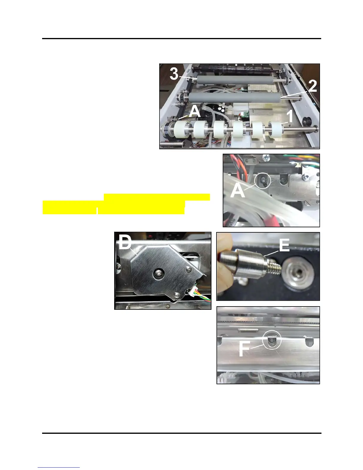
Remove the Output Print Roller:
1. Loosen Idler/Tensioner Roller [A]
mounting screw (located on Non-
Operator side) to release tension on
the Paper Path Drive Belt.
2. Remove the Encoder Guard and
Paper Path Encoder Wheel [D].
Remove the Encoder Shaft Extension
[E]. Hold the Extension with pliers
and unscrew while holding the Roller
in place. (You may have to remove
the Ink Drip Tray and Exit Guide Top
Assembly for access.)
3. Remove (1) screw [F] securing the Bearing to Non-Operator
Side Frame.
4. Disengage the Output Roller Pulley from the Paper Path Drive
Belt and the Exit Conveyor Belt and remove the Output Roller
[3] from the Printer.
Install in reverse order. NOTE: Check/adjust tension on the Belts.
See “Paper Path Roller Belt Tension Adjustment” in the
Adjustments Section. System Test: Press Printzone Test.
 Loading...


