SECTION 5
DISASSEMBLY AND ASSEMBLY
74
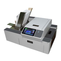
Non-Operator Side:
1. Unhook (2) Springs [H]
from the Upper Mounts on
the Printer Side Frame.
2. Remove (4) screws [I]
securing Top Assembly
Hinge Pins to the Media
Thickness Lift Frame.
3. Remove (2) screws [J]
securing the Hold-down
Wheels Support to the
Lift Frame.
4. Remove (4) screws [K]
securing the Lift Frame
to the Lift Supports.
5. Remove the Lift Frame from the Printer.
Eccentric Shafts:
1. Remove set screw [L] securing the Eccentric Cam to the shaft. Slide
the Shaft out of the Printer.
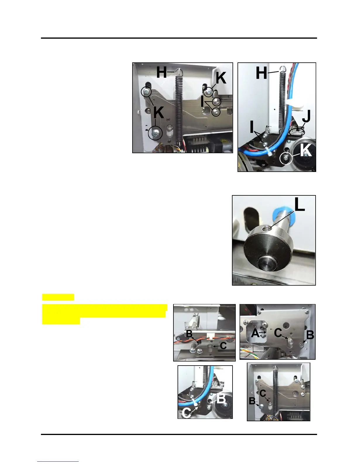
2. Reinstall in reverse order. IMPORTANT! Make sure the lobes on
the Cam face the same way at both ends of the shaft. Once
installed make sure the all of the cams on both shafts face the
same way.
Lubrication:
When reassembling the Media Thickness Adjustment
Assembly, apply a dab of white lithium grease to the
following areas:
[A] Along the frame edge contacted by the
restrainer screw.
[B] On the Support Shafts.
[C] On (4) Lift Cams on the Eccentric Shafts.
 Loading...


