UM10360 All information provided in this document is subject to legal disclaimers. © NXP B.V. 2013. All rights reserved.
User manual Rev. 3 — 19 December 2013 256 of 841
NXP Semiconductors
UM10360
Chapter 11: LPC176x/5x USB device controller
11.15.1 Transfer terminology
Within this section three types of transfers are mentioned:
1. USB transfers – transfer of data over the USB bus. The USB 2.0 specification refers
to these simply as transfers. Within this section they are referred to as USB transfers
to distinguish them from DMA transfers. A USB transfer is composed of transactions.
Each transaction is composed of packets.
2. DMA transfers – the transfer of data between an endpoint buffer and system memory
(RAM).
3. Packet transfers – in this section, a packet transfer refers to the transfer of a packet of
data between an endpoint buffer and system memory (RAM). A DMA transfer is
composed of one or more packet transfers.
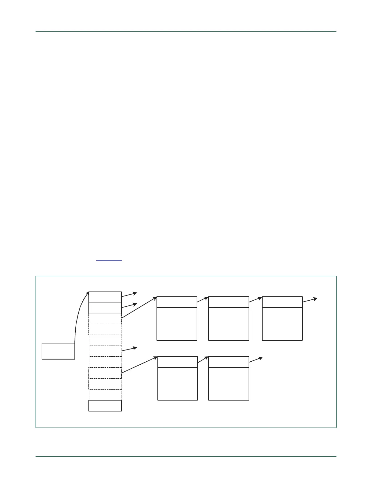
11.15.2 USB device communication area
The CPU and DMA controller communicate through a common area of memory, called the
USB Device Communication Area, or UDCA. The UDCA is a 32-word array of DMA
Descriptor Pointers (DDPs), each of which corresponds to a physical endpoint. Each DDP
points to the start address of a DMA Descriptor, if one is defined for the endpoint. DDPs
for unrealized endpoints and endpoints disabled for DMA operation are ignored and can
be set to a NULL (0x0) value.
The start address of the UDCA is stored in the USBUDCAH register. The UDCA can
reside at any 128-byte boundary of RAM that is accessible to both the CPU and DMA
controller.
Figure 30
illustrates the UDCA and its relationship to the UDCA Head (USBUDCAH)
register and DMA Descriptors.
Fig 30. UDCA Head register and DMA Descriptors
UDCA HEAD
REGISTER
1
31
DDP-EP2
2
DD-EP2-a
NULL
NULL
Next_DD_pointer
0
NULL
DDP-EP31
NULL
DDP-EP16
16
NULL
DD-EP2-b
Next_DD_pointer
DD-EP2-c
Next_DD_pointer
DD-EP16-a
Next_DD_pointer
DD-EP16-b
Next_DD_pointer
UDCA

 Loading...


