UM10360 All information provided in this document is subject to legal disclaimers. © NXP B.V. 2013. All rights reserved.
User manual Rev. 3 — 19 December 2013 435 of 841
NXP Semiconductors
UM10360
Chapter 19: LPC176x/5x I2C0/1/2
19.6.4 Slave Transmitter mode
The first byte is received and handled as in the slave receiver mode. However, in this
mode, the direction bit will be 1, indicating a read operation. Serial data is transmitted via
SDA while the serial clock is input through SCL. START and STOP conditions are
recognized as the beginning and end of a serial transfer. In a given application, I
2
C may
operate as a master and as a slave. In the slave mode, the I
2
C hardware looks for any of
its own slave addresses and the General Call address. If one of these addresses is
detected, an interrupt is requested. When the microcontrollers wishes to become the bus
master, the hardware waits until the bus is free before the master mode is entered so that
a possible slave action is not interrupted. If bus arbitration is lost in the master mode, the
I
2
C interface switches to the slave mode immediately and can detect any of its own slave
addresses in the same serial transfer.
19.7 I
2
C implementation and operation
Figure 90 shows how the on-chip I
2
C-bus interface is implemented, and the following text
describes the individual blocks.
19.7.1 Input filters and output stages
Input signals are synchronized with the internal clock, and spikes shorter than three
clocks are filtered out.
The output for I
2
C is a special pad designed to conform to the I
2
C specification.
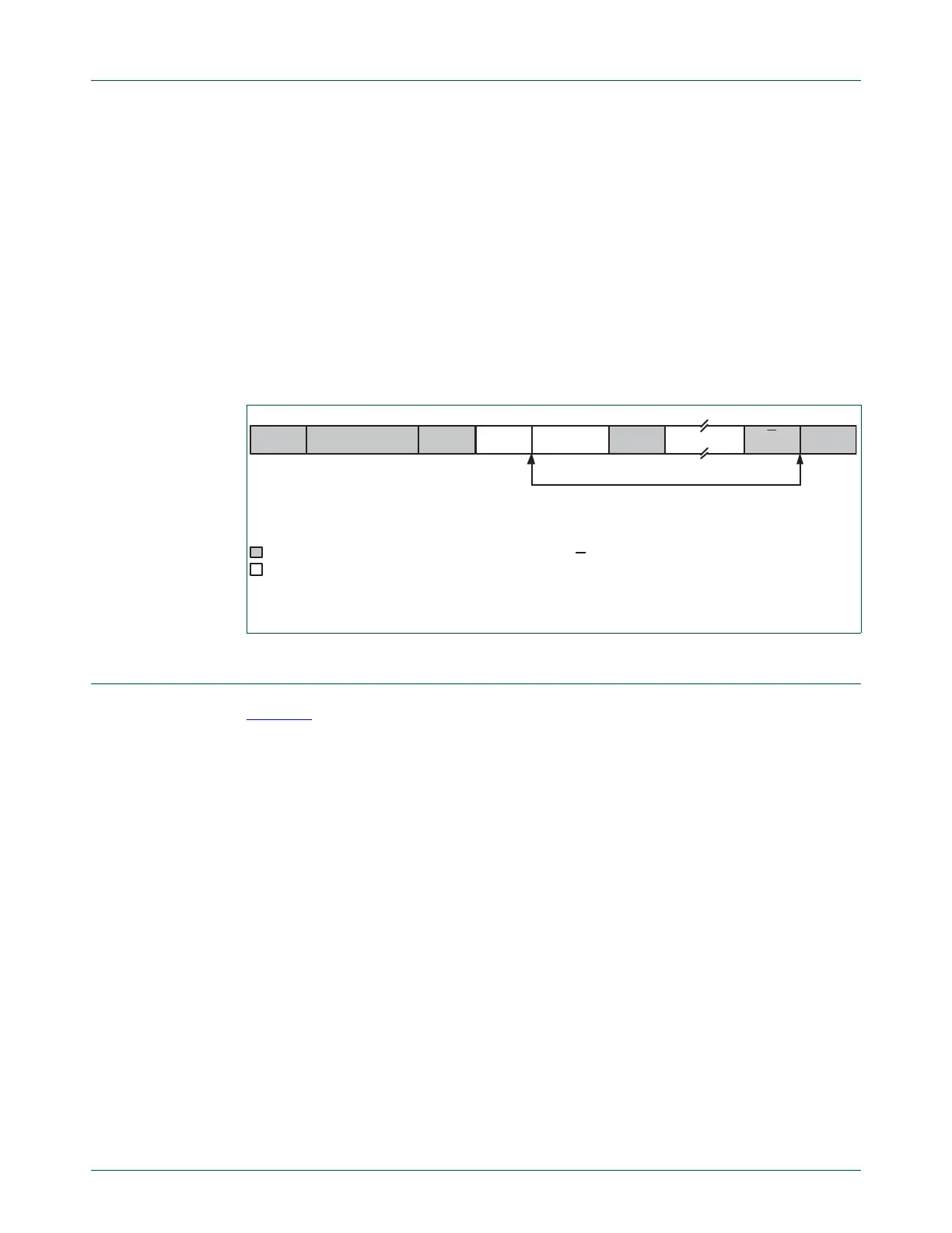
Fig 89. Format of Slave Transmitter mode
DATA
A = Acknowledge (SDA low)
A = Not acknowledge (SDA high)
S = START condition
P = STOP condition
A DATA
n bytes data transmitted
from Master to Slave
from Slave to Master
S SLAVE ADDRESS RW=1 A P
A

 Loading...


