CIBANO 500 PTM User Manual
176 OMICRON
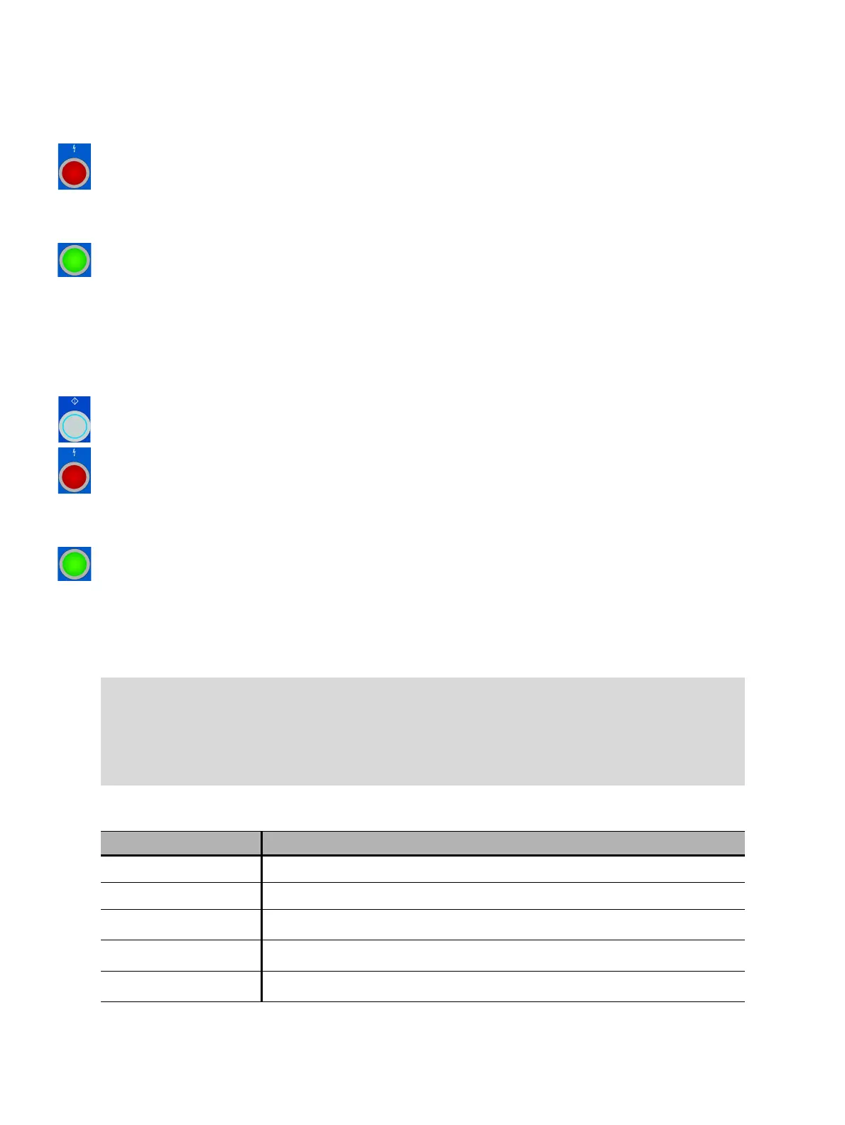
5. Start the measurement by pressing the Start/Stop button.
The blue ring on the Start/Stop button flashes for approx. 3 seconds, and the lightning symbol in
Primary Test Manager and the red status light on the front panel are flashing.
Note: You can abort the measurement anytime manually by pressing the Emergency Stop button
or the Start/Stop button on the CIBANO 500 front panel.
6. After the measurements have finished, the lightning symbol in Primary Test Manager stops flashing,
the green status light is on, and Primary Test Manager displays the measurement results.
7. For the measurement results, see Table 17-37: "Contact Resistance measurement data" later in this
section.
If you selected the Compensate ground loop resistance check box, proceed as follows:
1. Open the circuit breaker.
2. In the Measurements area of Primary Test Manager, select the breaker state Open.
3. In the Measurements area, click Start all.
The blue ring on the Start/Stop button is on.
4. Start the measurement by pressing the Start/Stop button.
The blue ring on the Start/Stop button flashes for approx. 3 seconds, and the lightning symbol in
Primary Test Manager and the red status light on the front panel are flashing.
Note: You can abort the measurement anytime manually by pressing the Emergency Stop button
or the Start/Stop button on the CIBANO 500 front panel.
5. After the measurements have finished, the lightning symbol in Primary Test Manager stops flashing,
the green status light is on, and Primary Test Manager displays the measurement results.
Note: If the circuit breaker has an even number of interrupters per phase, the test is typically performed
with the circuit breaker grounded on both ends. In this case no compensation is needed because the
voltages of the two channels of each CB MC2 module cancel out each other which results in no current
through the ground loop.
Tips & Tricks: The connection to the center point between two circuit breaker’s interrupters can be
tricky.If you are not sure whether the connection you have made is good, you can verify the connection
as follows. Perform a measurement with only channel 1, then a measurement with channel 2, and
finally a measurement with both channels. If the results match you have a perfect center point
connection. If the results do not match you either have a bad center connection or the effect of the
ground loop, that affects the result only when measuring asymmetrically, is too big.
Table 17-37: Contact Resistance measurement data
Data Description
Channel Channel of the CB MC2 module
Phase Measured phase
IDC
1
DC test current with the circuit breaker open
VDC
1
Measured voltage with the circuit breaker open
R open
1
Measured resistance with the circuit breaker open

 Loading...


