3-5
Electrical Connections
Use the following information to understand the AMR's electrical connections.
3-5-1
User Connections Area
The following information describes items in the User Connections Area. These items are typically
used when integrating a payload system with the AMR.
Precautions for Correct Use
Do not place additional components in the User Connections area.
Additional Information
• If covers or other items are removed from the AMR (Top Plate, User Connection cover, Oper-
ator Panel, etc.), the IP rating will be compromised. Take measures to ensure all openings
are properly covered to maintain the desired IP rating of the system.
• Refer to Section 2 Specifications on page 2-1 for more information about connector and
electrical specifications.
A cover must be removed to access this area. This requires a 4 mm hex key to remove the six M6
screws.
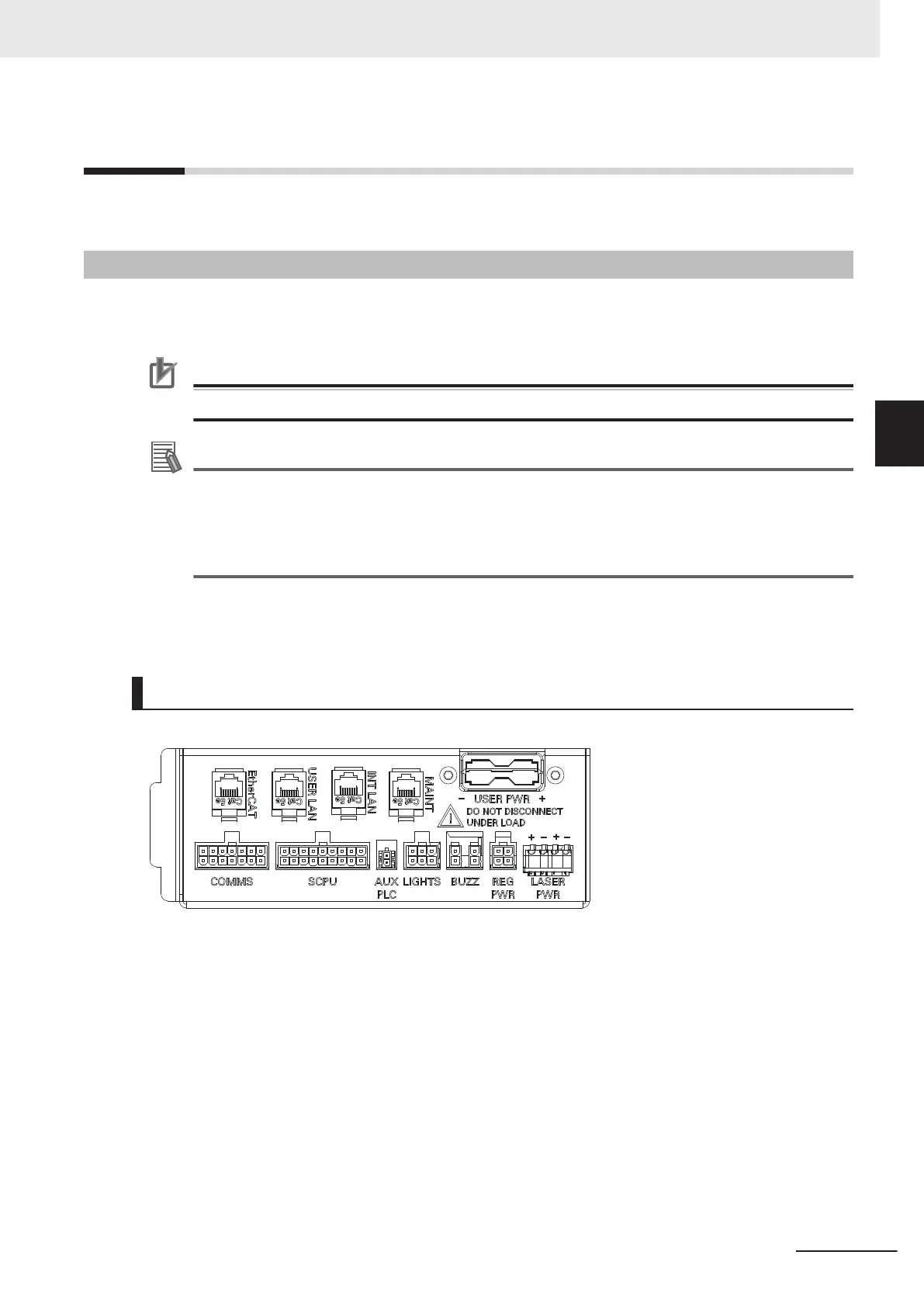
Connector Panel
The following information describes the items found on the Connector Panel.
EtherCAT
The EtherCAT connector provides a method to extend the EtherCAT network. It is typically used to
expand I/O capacity for the AMR.
USER LAN
The USER LAN connector in the User Connections area is used to establish a connection to the
NX102 controller.
The default IP address of the NX102 controller is 172.16.0.220.
INT LAN
The INT LAN connector in the User Connections area provides network connections for optional
side lasers or other peripheral accessories.
3 Installation
3-19
AMR (Autonomous Mobile Robot) MD-series Platform User's Manual (I681)
3-5 Electrical Connections
3
3-5-1 User Connections Area

 Loading...


