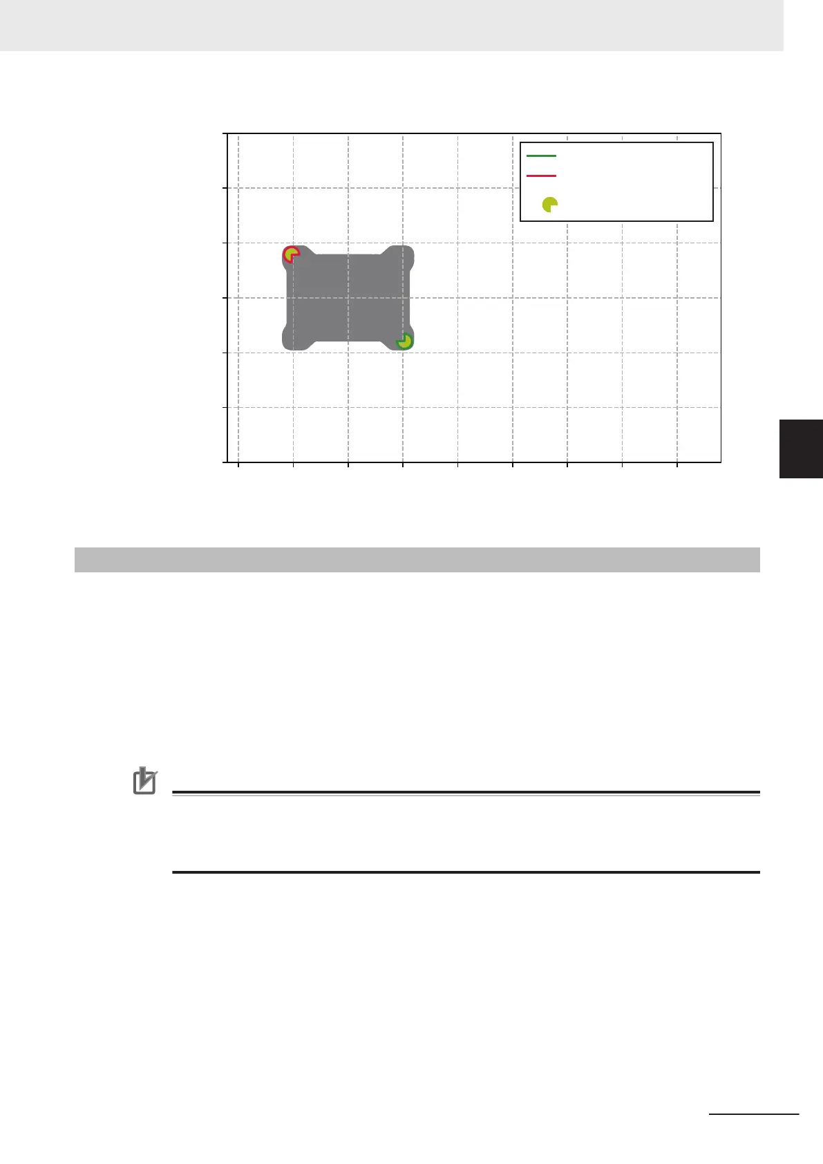
Safety Zone Pair 37
AMR X-axis
AMR Y-axis
1500
1000
500
0
-500
-1000
-1500
-1000 0
1000
2000 3000
Front Zone
Rear Zone
Safety Laser Scanners
-500
500
1500
2500
4-25-2
Alternate Safety Laser Scanner Zones
The AMR is equipped with a pair of safety-rated Alternate Safety Zone inputs that can be used to tog-
gle Safety Laser Scanner Zones between a default configuration or an alternate configuration. This
may be useful if the payload varies in size for certain applications.
These inputs are located on the SCPU connector in the User Connections area. Refer to SCPU on
page 3-20 for more information.
The alternate Safety Laser Scanner zones are identical to the default zones when the default configu-
ration is present. Activating the alternate zones has no effect until new zones are created. Contact
your local OMRON representative for a Safety Laser Scanner zone generation tool.
Precautions for Correct Use
If alternate Safety Laser Scanner Zones are used for varying payload sizes, an alternate AMR
footprint should also toggle for navigation purposes. Refer to the Fleet Operations Workspace
Core User's Manual (Cat. No. I635) for more information about configuring the AMR footprint
clearances.
4 Operation
4-73
AMR (Autonomous Mobile Robot) MD-series Platform User's Manual (I681)
4-25 Safety Laser Scanner Zones
4
4-25-2 Alternate Safety Laser Scanner Zones

 Loading...


