Light Discs and Light Strips
You must ensure that the payload does not block the light discs, or front or back light strips as they
provide visual indication of the AMR movement.
Access to User Connections Area
Connectors such as the MAINT port may need to be readily accessible without removing the pay-
load structure. Design the payload structure for easy access to the User Connections area or ex-
tend the port to a new location on the payload structure. Refer to 3-12 Maintenance Port Extension
Procedure on page 3-44 for more information.
1-8-2
Power Consumption
Any electrical devices on your payload structure that consume significant power will noticeably shorten
the AMR's run time. Examples of power-consuming payload structures are robotic arms or a motorized
conveyor.
Momentary current spikes that are over the thresholds specified below will activate current limiting pro-
tection and cause power loss at the USER power connector. Simultaneous inrush loads might trip the
over current protection at the battery. Use external current limiting devices to prevent transient current
overload.
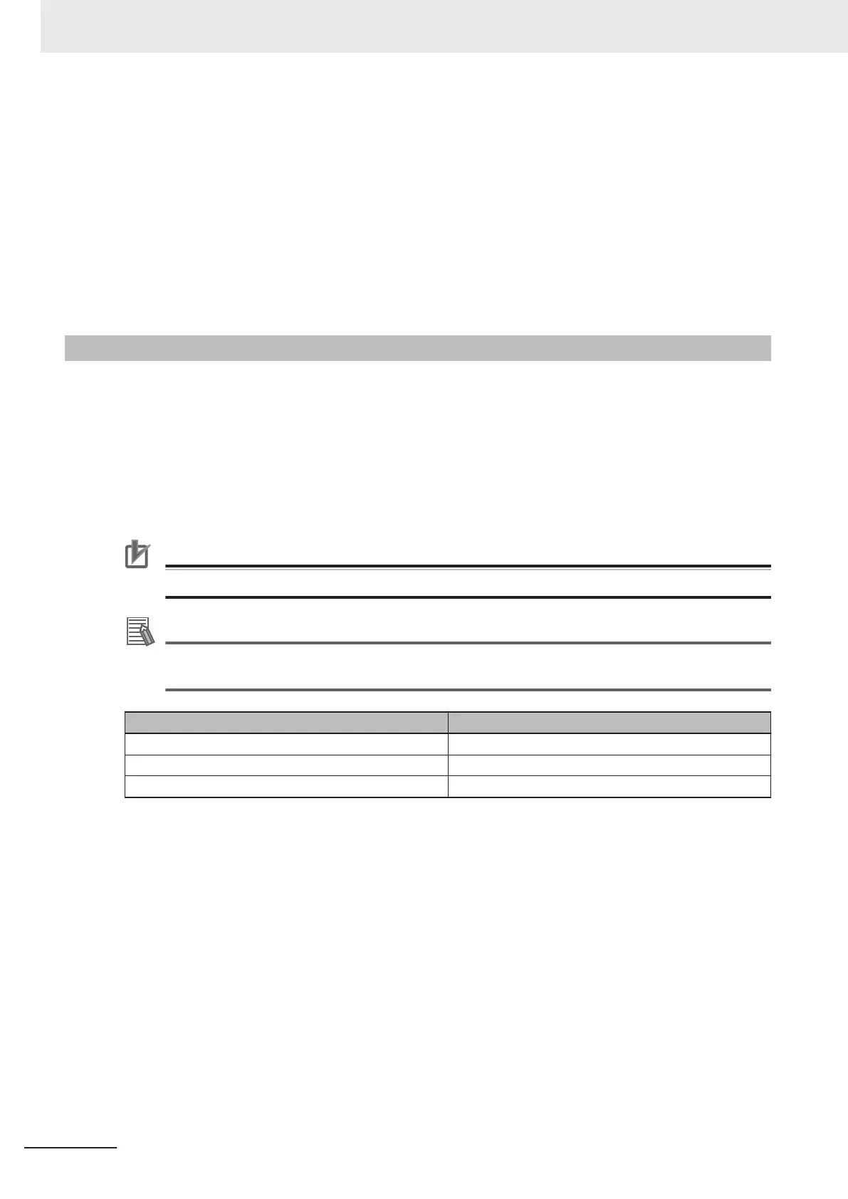
Precautions for Correct Use
Minimize payload power consumption whenever possible to prevent excessive battery drain.
Additional Information
Refer to the power limits specified in 2-4-7 USER PWR Connector on page 2-17 and
2-4-13 REG PWR Connector on page 2-19 for more information.
Overload Duration Overcurrent Level
Continuous 40 A
100 ms 100 A
Instantaneous 150 A
1 Overview
1-38
AMR (Autonomous Mobile Robot) MD-series Platform User's Manual (I681)