3-6
Attaching the Payload
Use the information in this section to understand design considerations and other factors for attaching
a payload to the AMR.
Precautions for Safe Use
You must perform a complete risk assessment for your payload design and the intended use of
the AMR prior to its operation.
3-6-1
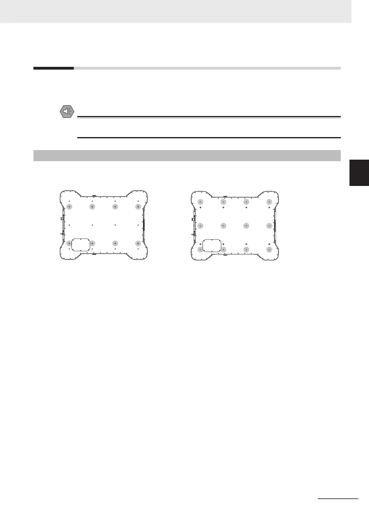
Payload Structure Mounting Points
Several payload structure mounting points are provided on the top of the AMR.
M16 Mounting Points M6 Mounting Points
These mounting points allow for positioning of the payload to achieve maximum stability with various
payload designs.
Refer to the following sections for more information.
• 2-2-4 Payload Center of Gravity on page 2-7
• Payload Structure Mounting Point Dimensions on page 2-6
Make the following considerations when using payload structure mounting points.
• Use mounting screws appropriate for the mass of your payload.
• Ensure that the mechanical connection points as well as the electrical connections are conveniently
accessible.
• M16 x 2.0 mounting points have a torque limit of 70 N m.
• M16 x 2.0 mounting points have a maximum thread depth of 27 mm with a Top Plate present and 24
mm without a Top Plate present.
• M16 x 2.0 mounting points have a maximum allowable tension force of 10 kN.
• Only the following M16 x 2.0 mounting points can be used simultaneously to lift the AMR. These are
rated to lift the AMR without a payload. Refer to 6-5 Lifting the AMR on page 6-7 for more infor-
mation.
3 Installation
3-27
AMR (Autonomous Mobile Robot) MD-series Platform User's Manual (I681)
3-6 Attaching the Payload
3
3-6-1 Payload Structure Mounting Points

 Loading...


