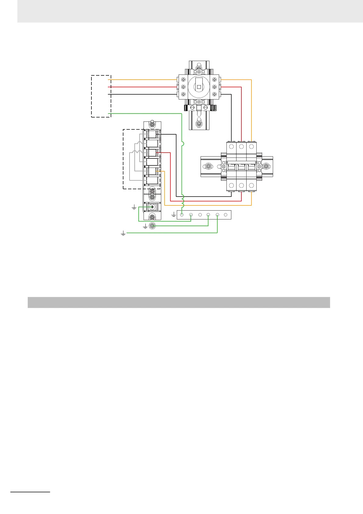
Delta Configuration
A
C
B
BN
CN
Delta
Jumper
Arrangement
AN
User-supplied
Connections
L2
L1
L3
GND
To Door
Ground
Point
(A)
(B)
(C)
(D)
(A) Disconnect Switch
(B) Terminal Strip
(C) Circuit Breakers
(D) Ground Bar
3-2-5
Commissioning Procedure
Use the following procedure to commission the Power Supply Box.
1 Prepare the facility AC supply and its disconnect switch.
2 Make sure that the facility power is in the OFF state.
3 Make sure that the Main Disconnect Switch located on the electrical access panel is in the OFF
(horizontal) position.
4
Wire the facility power to the electrical access panel as detailed in 3-2-4 Electrical Connections
on page 3-7. You must make sure to adjust the jumpers as required for the voltage range.
5
Once the wiring is complete and the facility power cable is connected to the electrical access
panel properly, you can enable the AC facility power.
6 Confirm that the circuit breakers inside the electrical access panel are in ON positions (top / up
position).
3 Installation
3-10
AMR (Autonomous Mobile Robot) MD-series Platform User's Manual (I681)

 Loading...


