• The AMR must be turned OFF and the disconnect switch must be in the OFF position.
The following components are required for this procedure (included with double sensor HAPS kit
73925-020).
• Rear HAPS sensor.
• M12 to Mini FIt Jr. cable (2 m).
• Two M3 x 8 T10 screws.
• Heat shrink tubing.
The following tools and supplies are required for this procedure.
• T10 star bit.
• Torque wrench.
1 Remove the rear and right skins.
Refer to 6-11-1 Removing and Replacing Skins on page 6-17 for more information.
2
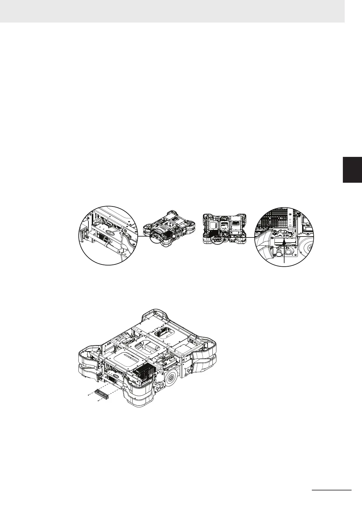
Route the cable as shown in the following figure and plug the Mini Fit Jr. connector into the
HAPS FORE port.
Do not route the cable in a position that can interfere with the mechanical brake release lever.
3 Place the HAPS sensor in the following position and then insert the M3 x 8 screws using a T10
star bit.
Apply a torque of 1 N-m.
4 Plug the M12 connector on the cable into the HAPS sensor.
5 Replace the rear and right skins to complete this procedure.
3 Installation
3-31
AMR (Autonomous Mobile Robot) MD-series Platform User's Manual (I681)
3-7 HAPS Installation and Configuration
3
3-7-2 Rear HAPS Sensor Installation
 Loading...


