Parts and FunctionsFP2/FP2SH
2 − 63
2.11 I/O Mixed Units Specifications
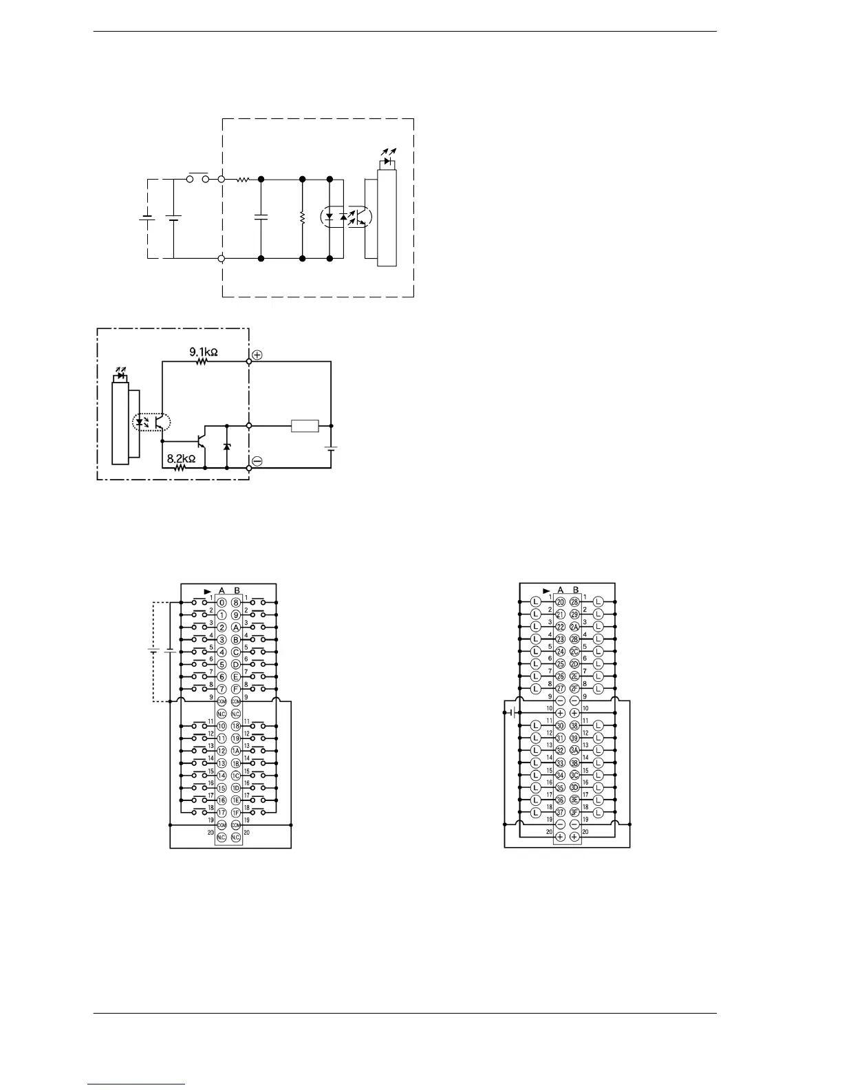
Internal Circuit Diagram
24V DC
Input
COM
Input indicator LED
Internal circuit
Input
5.6kΩ
560Ω
Internal circuit
Output indicator
LED
Output
Load
5 to 24V DC
Output
Pin Layout
5 to 24V DC
24V DC
Input X0 to X1F
Pin layout of first 32 points
Left side connector
Output Y20 to Y3F
Pin layout of last 32 points
Right side connector
The COM pins of each connector are
connected internally.
Although “+” and “
−” terminals are
connected internally with the same
connector. It is recommended that
they also be connected externally.