Installation and WiringFP2/FP2SH
4 − 31
4.4 Wiring the Connector Type I/O Units
RT-2 Relay Terminal
For 64-point type output unit (FP2−Y64T), you can connect four sets of the RT-2 relay
terminals with 16 outputs by using two-branch type cable.
For 32−point type output unit (FP2−Y32T) and output connector side of I/O mixed unit
(FP2−XY64D2T, FP2−XY64D7T), you can connect two sets of the RT-2 relay terminals
with 16 outputs by using two-branch type cable.
For connecting the terminal to the terminal block, use M3-sized pressure connection
terminals.
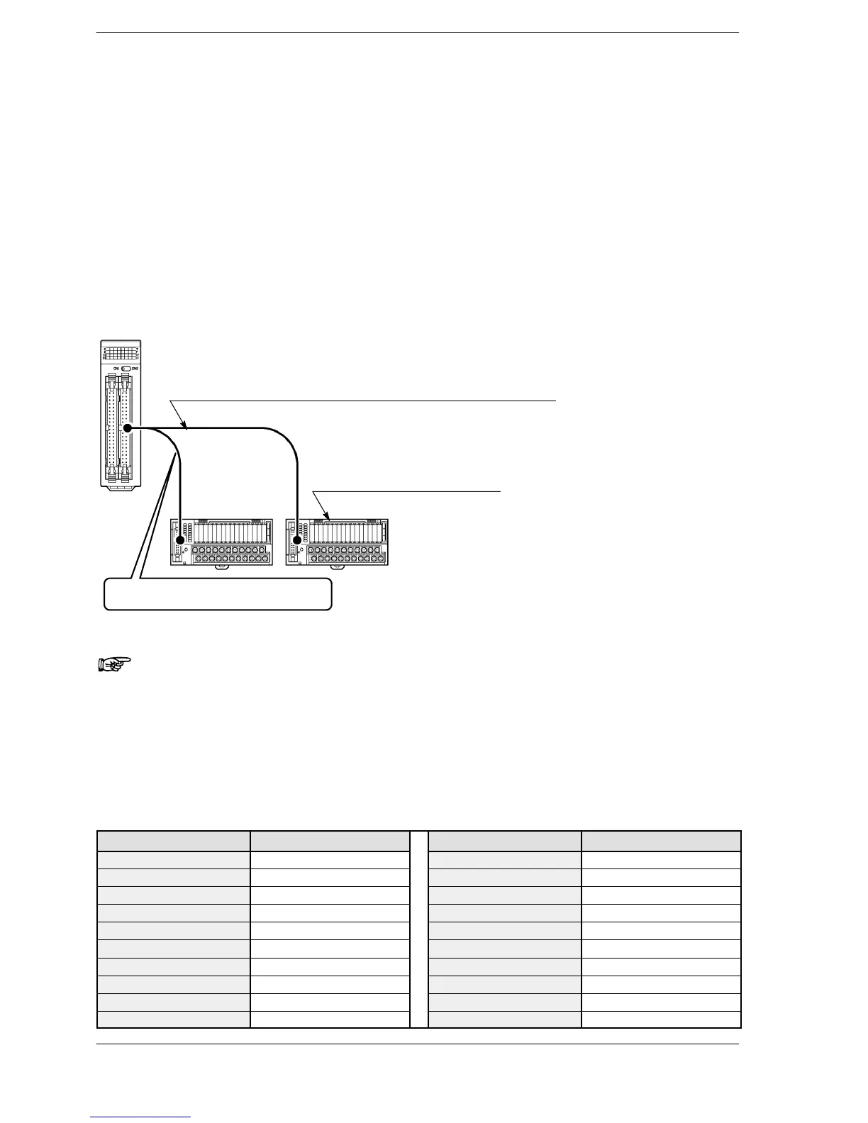
RT-2 relay terminal connection diagram for 32−point type and 64−point type out-
put units and I/O mixed units
Two-branch type cable for relay terminal (40 pins − 40 pins × 2)
RT-2 relay terminal (16 outputs)
(AY232502 or AY232522)
The relay terminal that is connected with the
shorter cable is the lower I/O number.
Note
24V DC should be supplied between the (+) and (−) terminals of
the relay terminal. Power is supplied to drive the relays of the ter-
minal itself. The I/O power supply supplied to the units and the
power supply supplied to the RT-2 relay terminals are the same
power supply.
Correspondence table of RT-2 relay terminal
Terminal number Output number Terminal number Output number
0+ Y0 8+ Y8
1+ Y1 9+ Y9
2+ Y2 A+ YA
3+ Y3 B+ YB
COM+ COM terminal for Y0 to Y3 COM+ COM terminal for Y8 to YB
4+ Y4 C+ YC
5+ Y5 D+ YD
6+ Y6 E+ YE
7+ Y7 F+ YF
COM− COM terminal for Y4 to Y7 COM− COM terminal for YC to YF