FP2/FP2SHOverview
1 − 6
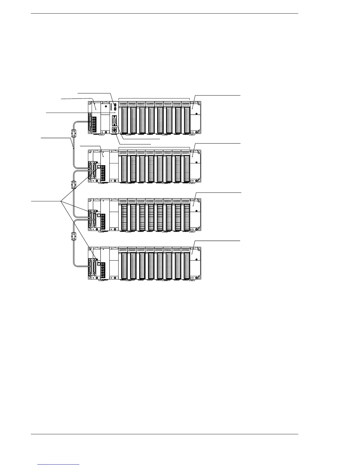
1.1 System Configuration
• Do not install a CPU on an expansion backplane.
• There is no need to make the number of modules on the ex-
pansion backplane equal to the number of modules on the
CPU backplane.
FP2 backplane H type
Power supply unit
CPU unit
Backup battery
Expansion memory
COM port
Tool port
I/O unit
Basic backplane
Expansion backplane 1
Power supply unit
Expansion cable
Expansion backplane 2
Expansion backplane 3
I/O unit
Board No. setting
switches
The basic FP2 backplane H type that the CPU unit can be installed and the expansion
backplane H type that only the I/O units and the intelligent I/O units can be installed are
available.
A maximum of eight I/O units (including the unit built in the CPU) can be controlled per
backplane. Even if further I/O units are installed, they are not recognized.
Up to three expansion backplanes can be added on for expansion.
Use the board No. setting switches on the board to distinguish the expansion back-
plane.
A power supply unit is also necessary on an expansion backplane.