FP2/FP2SHParts and Functions
2 − 38
2.9 Input Units Specifications
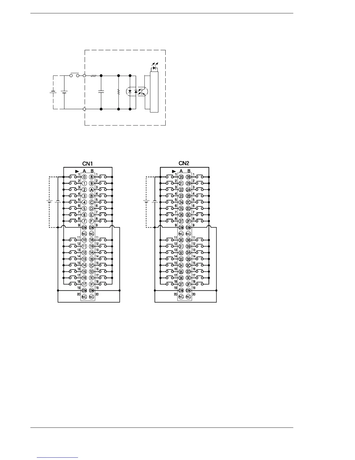
Internal Circuit Diagram
24V DC
Input
COM
Input indicator LED
Internal circuit
Input
5.6kΩ
560Ω
Pin Layout
Input X0 to X1F
Pin layout of first 32 points
Left side connector (CN1)
Input X20 to X3F
Pin layout of last 32 points
Right side connector (CN2)
24V DC
24V DC
The COM pins of each connector are connected internally.
For more information regarding the applicable connectors and terminals, refer to sec-
tion 4.4.1.