Parts and FunctionsFP2/FP2SH
2 − 57
2.11 I/O Mixed Units Specifications
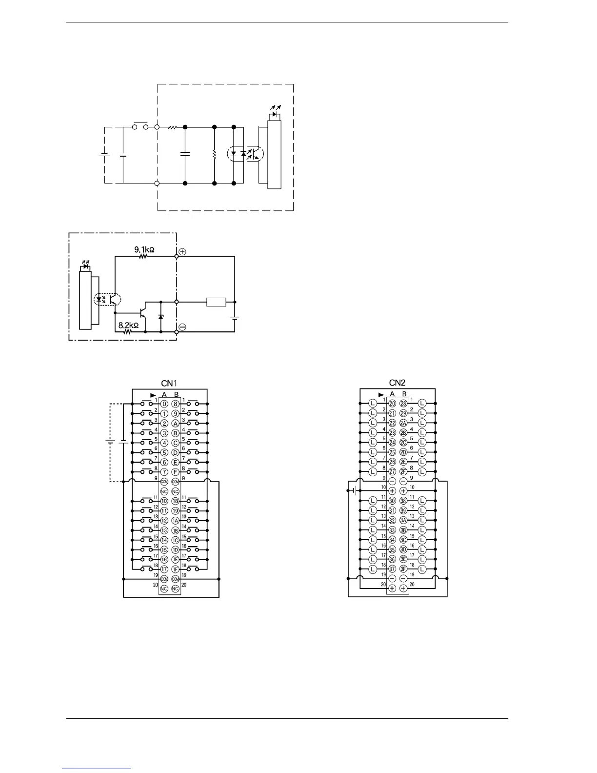
Internal Circuit Diagram
24V DC
Input
COM
Input indicator LED
Internal circuit
Input
5.6kΩ
560Ω
Internal circuit
Output indicator
LED
Output
Load
5 to 24V DC
Output
Pin Layout
5 to 24V DC
24V DC
Although ”+” and “−” terminals are
connected internally with the same
connector. It is recommended that
they also be connected externally.
The COM pins of each connector are
connected internally.