Chapter 2: Troubleshooting Your Library
Interpreting LEDs
Quantum Scalar i6000 User’s Guide 97
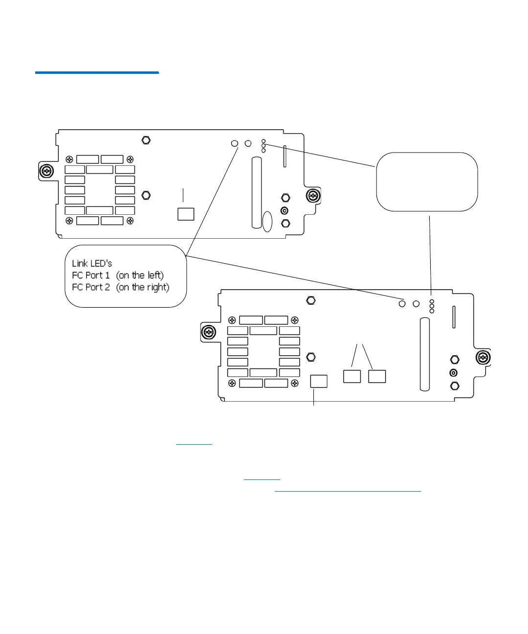
Figure 25 Rear View of Fibre
Channel Drive Sled (UDS-3 LTO-
4 and LTO-5 Drives)
Tab l e 10 on page 98 describes how to interpret the drive sled status LED
activity that you might see on the rear of a UDS-2 or UDS-3 drive sled.
For a description of how the blade status LEDs appear under normal
conditions, see
Tab l e 11 on page 98. For information about interpreting
the drive link LED, see Drive Sled Fibre Channel Link LED on page 99.
- top = blue
- middle = amber
- bottom = green
status LEDs:
fibre ports
12
fibre port
LTO-4
LTO-5
EEB port