Chapter 2: Troubleshooting Your Library
Interpreting LEDs
Quantum Scalar i6000 User’s Guide 101
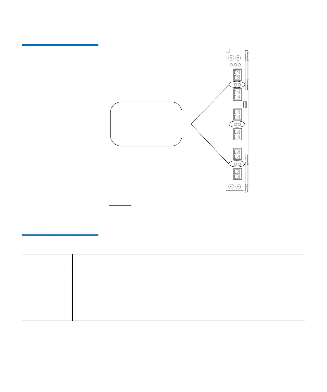
Figure 26 Locations - Colors of
I/O Blade Fibre Port Link LEDs
Tab l e 14 on page 101 describes how to interpret the link LED activity
that you might see. There is one supported model of FC I/O blade: 7404.
LED behavior varies based on which model is installed in the library.
Table 14 FC I/O Blade Link LED
States
Note: For the 7404 FC I/O blade, fibre port LEDs are off while the
blade is booting up.
I/O blade link LEDs
- left = green (belongs
to port below)
- right = green (belongs
to port above)
FC I/O Blade
Model
Possible Green LED States and Explanations
7404
4 gigabit/sec
• Solid on — the FC I/O blade has established a link but is not currently
transporting data.
• Blinks — the link is active and is currently transporting data.
• Solid off — the FC I/O blade has not established a link OR the link is active and is
currently transporting a large amount of data.
 Loading...


