Chapter 13: Running Your Library
Understanding Location Coordinates
Quantum Scalar i6000 User’s Guide 469
• Bay — The bays in the I/O management unit as viewed from the rear
of the library. There are eight bays in the I/O management unit. Bay
1 is on the lower left and is not populated. Bay 2 always contains
the control management blade (CMB). Bays 3 through 6 can contain
FC I/O blades and bays 7 and 8 can contains Ethernet Expansion
blades. See
Figure 57.
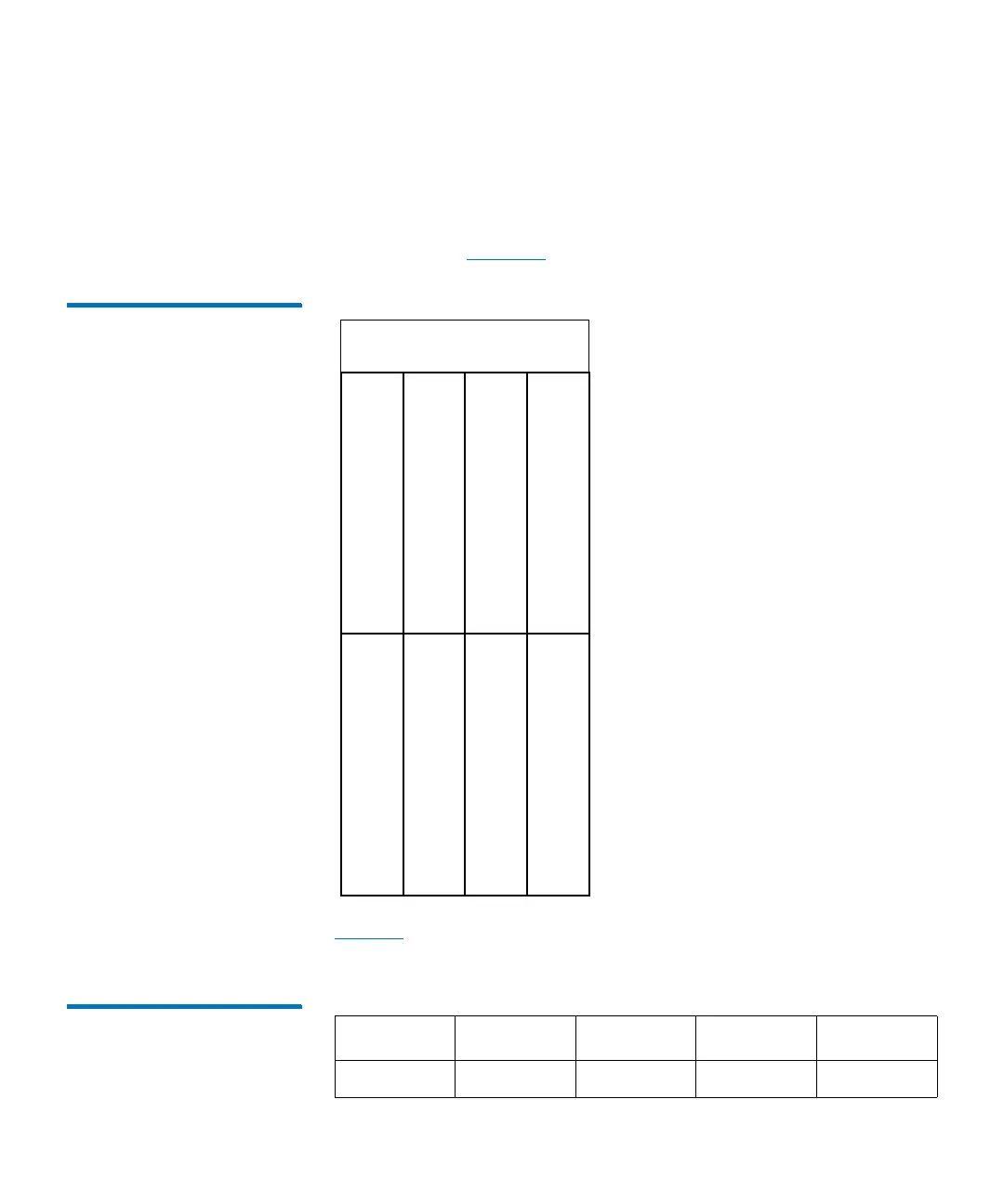
Figure 57 I/O Management
Unit Bay Numbering
Tab l e 41 lists the range of possible FC I/O blade or EEB location
coordinates.
Table 41 FC I/O Blade/EEB
Location Coordinates
bay 1 (not used)
bay 3 (first FC I/O blade)
bay 5 (third FC I/O blade)
bay 4 (second FC I/O blade)
bay 6 (fourth FC I/O blade)
bay 8 (EEB), upper drive
cooling assembly
bay 7 (EEB, lower drive
bay 2 (CMB)
cluster) cluster)
1 1-16 1 1 3-8
Aisle Module Rack Cluster Bay