Rockwell Automation Publication 193-UM015D-EN-P - February 2015 47
Installation and Wiring Chapter 2
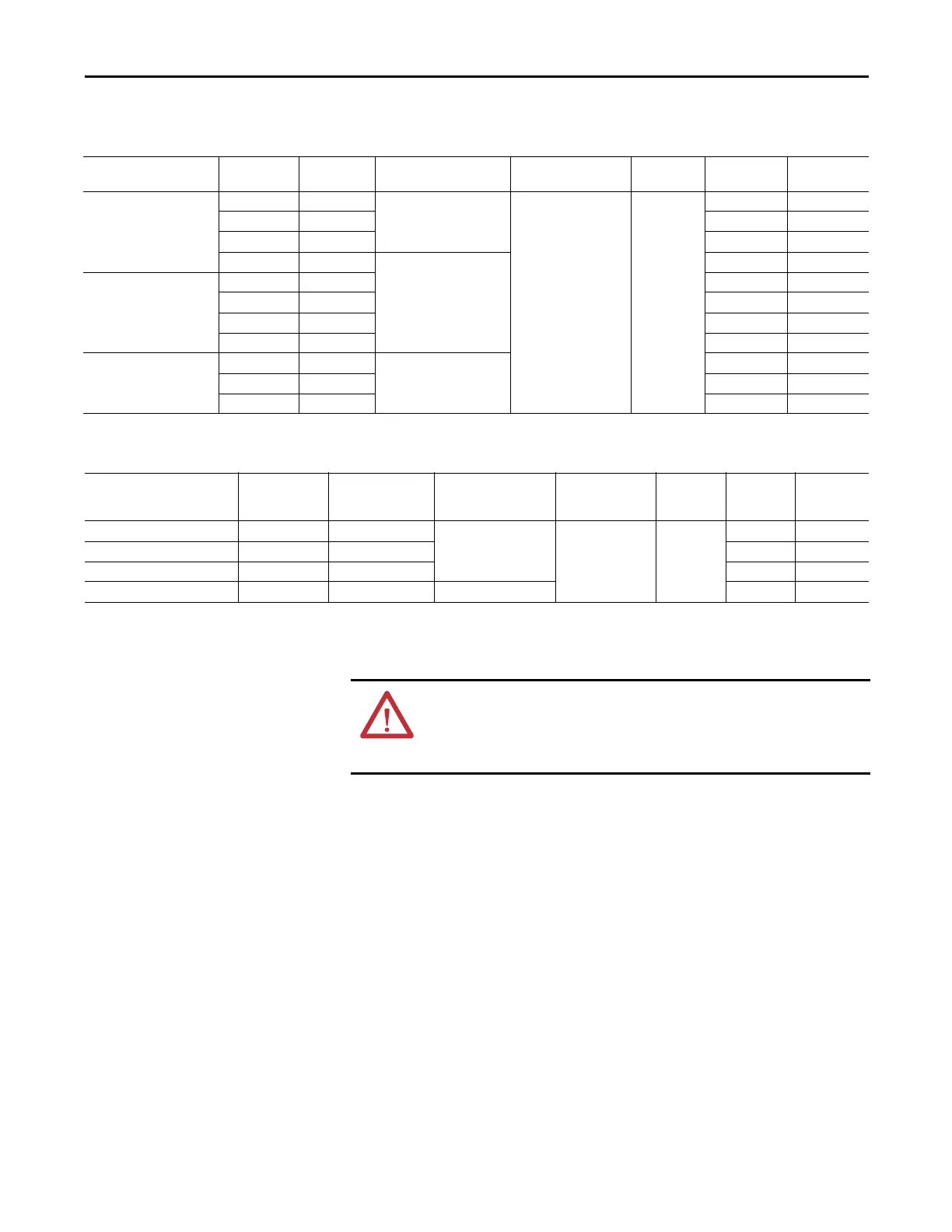
Table 11 - Type 1 and Type II fuse coordination with Bul. 100-C and 100-D contactors per
EN60947-4-1
Table 12 - Type 1 and Type II fuse coordination with Bul. 100-C and 100-D contactors
per EN60947-4-1
Typical Motor Connections
Three-Phase Direct On-Line (DOL) and Single-Phase Full-voltage
The following wiring diagram illustrates the E300 Electronic Overload Relay
typical motor connections in a three-phase DOL and single-phase full-voltage
applications.
Overload Relay with
Sensing Module Cat. No.
Contactor Cat.
No.
Max. Starter
FLC[A]
Prospective Short-Circuit
Current, I
r
[A]
Conditional Short-
Circuit Current, I
q
[A]
Max. Voltage
[V]
Type I Class J or
CC Fuse [A]
Type II Class J
or CC Fuse [A]
193-ESM-___-30A-C23
100-C09 9
1000
100,000 600
20 15
100-C12 12 20 20
100-C16 16 30 30
100-C23 23
3,000
40 40
193-ESM-___-30A-C55,
193-ESM-___-60A-C55
100-C30 30 50 50
100-C37 37 50 50
100-C43 43 70 70
100-C55 55 80 80
193-ESM-___-100A-C97
100-C72 72
5,000
100 100
100-C85 85 150 150
100-C97 97 200 200
Overload Relay with Sensing
Module Cat. No.
Contactor Size Max. Starter FLC[A]
Prospective Short-
Circuit Current, I
r
[A]
Conditional Short-
Circuit Current, I
q
[A]
Max. Voltage
[V]
Type I Class J
Fuse [A]
Type II Class J
Fuse [A]
592-ESM-___-30A-S2 0 18
3,000
100,000 600
30 30
592-ESM-___-30A-S2 1 27 30 30
592-ESM-___-60A-S2 2 45 60 60
592-ESM-___-100A-S3 3 90 5,000 200 200
ATTENTION: When working on energized circuits, DO NOT rely on voltage and
current information that is provided by the E300 Electronic Overload Relay for
personal safety. Always use a portable voltage or current measurement device
to measure the signal locally.
 Loading...


