Rockwell Automation Publication 193-UM015D-EN-P - February 2015 31
Installation and Wiring Chapter 2
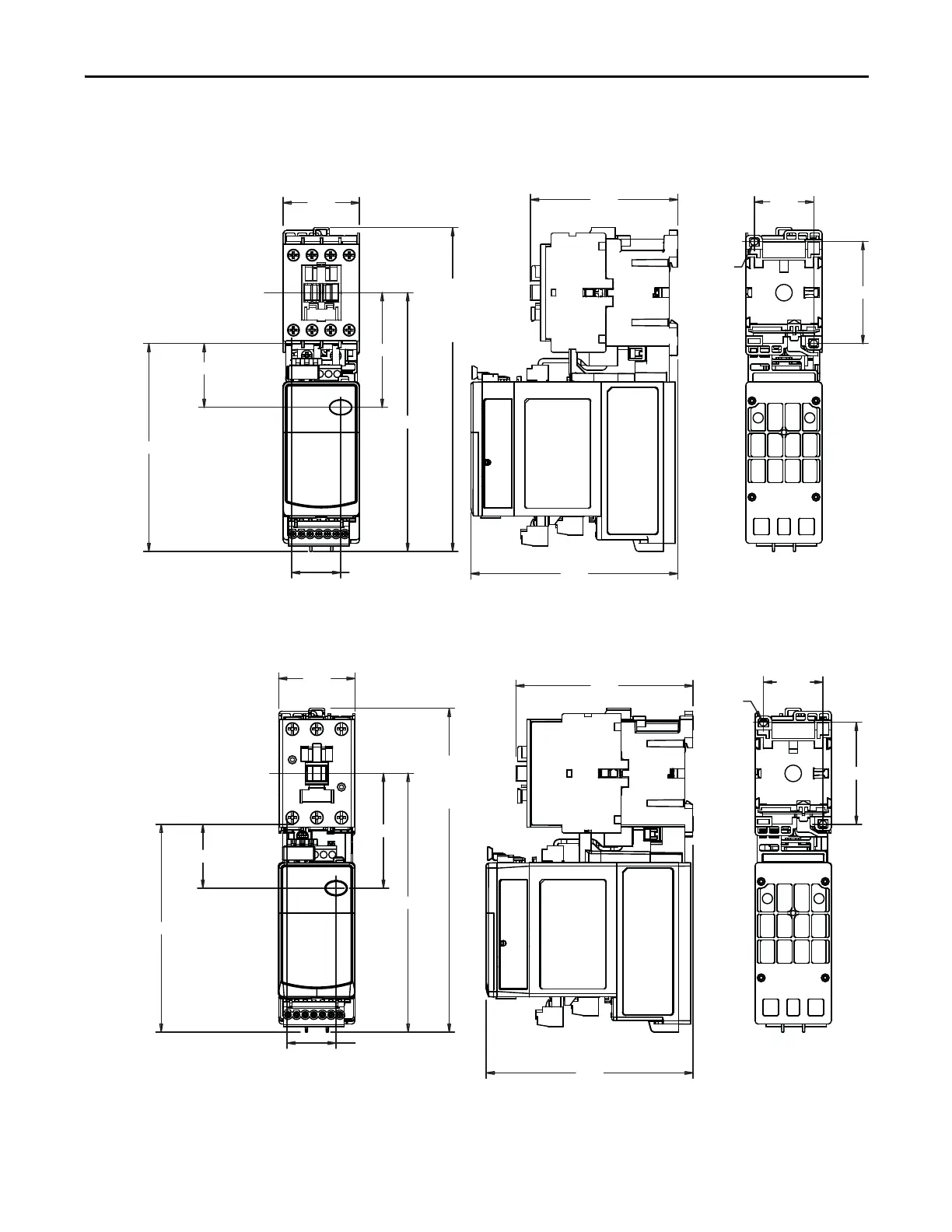
Starter Dimensions
Approximate dimensions are shown in millimeters (inches). Dimensions are not
intended to be used for manufacturing purposes.
Figure 14 - E300 Sensing Module 193-ESM-___-__-C23 with 100-C09…-C23 Contactor
Figure 15 - E300 Sensing Module 193-ESM-___-__-C55 with 100-C30…-C37 Contactor
45
(1.76)
87
(3.40)
60 (2.3
35
(1.37)
n 5 (0.18)
190 (7.49)
37 (1.47)
122 (4.81)
29 (1.14)
122
(4.78)
152 (5.98)
67 (2.65)
FROM
CONTACTOR
MTG. HOLE
FROM
CONTACTOR
MTG. HOLE
(ADD 5 mm (0.19 in.)
FOR CONTACTOR COIL
ON LINE SIDE)
37 (1.48)
122 (4.81)
29 (1.13)
190 (7.49)
67 (2.65)
152 (5.98)
45
(1.76)
122
(4.78)
104
(4.10)
35
(1.374)
60 (2.36)
n 5 (0.18)
(ADD 5 mm (0.19 in.)
FOR CONTACTOR COIL
ON LINE SIDE)
FROM
CONTACTOR
MTG. HOLE
FROM
CONTACTOR
MTG. HOLE
 Loading...


