86 Rockwell Automation Publication 193-UM015D-EN-P - February 2015
Chapter 4 System Operation and Configuration
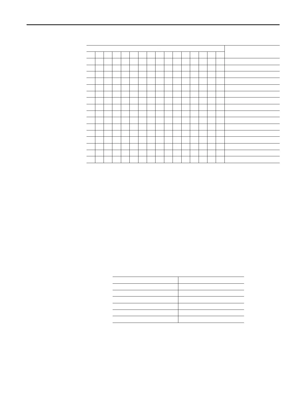
Table 54 - Emergency Start Bit Function Detail— Device Status 0 (Parameter 20)
Diagnostic Station User-
defined Screens
The E300 Electronic Overload Relay’s Diagnostic Station has four user-defined
screens that are part of the Diagnostic Station’s display sequence in which you can
define up to two parameters per screen.
User-defined Screen 1
User-defined Screen 1 – Parameter 1
User-defined Screen 1 - Parameter 1 (Parameter 428) is the E300 parameter
number to display for the first parameter in user-defined screen 1. You can select
one of the 560 available E300 Electronic Overload Relay parameters.
Table 55 - Screen 1 - Parameter 1 (Parameter 428)
User-defined Screen 1 – Parameter 2
User-defined Screen 1 - Parameter 2 (Parameter 429) is the E300 parameter
number to display for the second parameter in user-defined screen 1. You can
select one of the 560 available E300 Electronic Overload Relay parameters.
Bit
1514131211109876543210 Function
X Trip Present
X Warning Present
X Invalid Configuration
X Current Present
X GFCurrent Present
X Voltage Present
X Emergency Start Enabled
X DeviceLogix Enabled
X Feedback Timeout Enabled
X Operator Station Present
X Voltage Sensing Present
X Intern Ground Fault Sensing Present
X Extern Ground Fault Sensing Present
XPTC Sensing
XReady
Reserved
Default Value 1
Minimum Value 0
Maximum Value 560
Parameter Type UINT
Size (Bytes) 2
Scaling Factor 1
Units
 Loading...


