52 Rockwell Automation Publication 193-UM015D-EN-P - February 2015
Chapter 2 Installation and Wiring
Control Circuits
The E300 Electronic Overload Relay can provide motor control logic for many
different types of motor starters (see Chapter 5
for more information on
Operating Modes). By default, the E300 is configured for the Overload-Network
operating mode. The following wiring diagrams are typical control circuits for
Non-Reversing and Reversing Motor starters that use the Overload-Network
operating mode when Relay 0 (terminals R03 and R04) is configured to be a
normally closed Trip Relay.
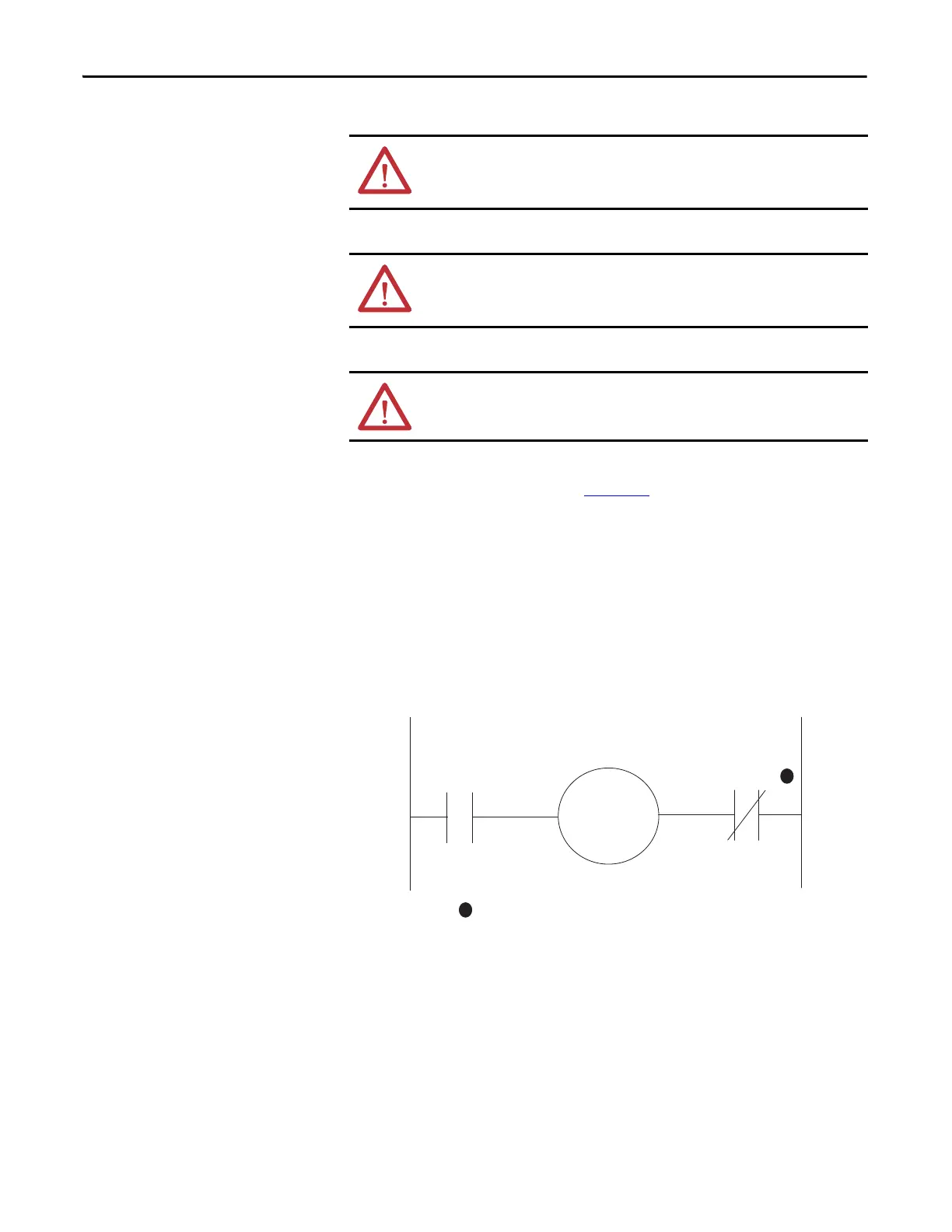
Full-Voltage Non-Reversing Starter (with Network Control)
Figure 38 - NEMA Nomenclature
ATTENTION: Do not exceed the ratings of the E300 Electronic Overload Relay’s
output and trip relay. If the coil current or voltage of the contactor exceeds the
overload relay’s ratings, an interposing relay must be used.
ATTENTION: When the power is applied to the E300 Electronic Overload Relay’s
A1 and A2 terminals, the N.O. relay contact that is assigned as a Trip Relay closes
after approximately 2 seconds if no trip condition exists.
ATTENTION: More control circuit protection may be required. See the
applicable electrical codes.
Relay 1
Relay 0
Configured as a
Trip Relay
R13 R14
A1
A2
M
R03
R04
1
1
Contact shown with supply voltage applied.
 Loading...


