Standard functions
SIMOCODE pro
10-6 GWA 4NEB 631 6050-22 DS 03
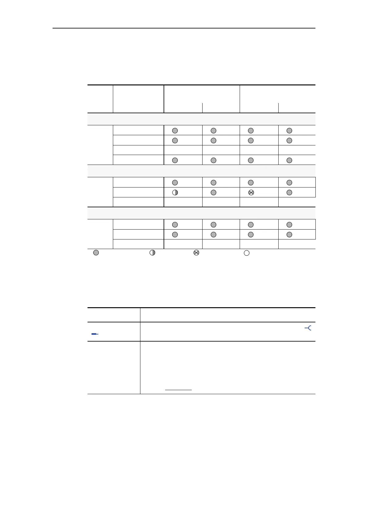
Test phases
The following table shows the test phases carried out when the "TEST/
RESET" button is pressed for the required length of time:
Te s t s e tt i n g s
Test
phase
Status Without main current With main current
O.K. Fault
1)
O.K. Fault
Hardware test/lamp test
< 2s
"DEVICE" LED Orange Green Orange Green
"GEN.FAULT" LED
Contactor control Unchanged Unchanged Unchanged Unchanged
Show QL
Results of the hardware test/lamp test
2s - 5s
"DEVICE" LED Green Red Green Red
"GEN.FAULT" LED
Contactor control Unchanged Deactivated Unchanged Deactivated
Relay test
> 5s
"DEVICE" LED Green Red Green Red
"GEN.FAULT" LED
Contactor control Deactivated Deactivated Deactivated Deactivated
LED lit/activated LED flashing LED flickering LED OFF
1) "Fault" only displayed after 2 s
Table 10-2: The states of the status LEDs/contactor controls during testing
Test 1 to 2 - Description
Input Control of the "Test" function block from any signal (any sockets ,
e.g. device inputs, control bits from PROFIBUS DP, etc.)
Test/Reset
buttons blocked
The blue Test/Reset buttons on the basic unit and the operator
panel are usually intended for acknowledging faults and for carrying
out a device test.
The buttons can be blocked via "Test/Reset buttons blocked". These
can then be used for other purposes. On the operator panel with
display, blocking is carried out via the corresponding menu function.
(Default: Unblocked
)
Table 10-3: Test settings