Logic modules
SIMOCODE pro
11-24 GWA 4NEB 631 6050-22 DS 03
Functional principle
The limit signal issued depends on
• The operating state of the motor
• The TPF function
• The parameterized "Activity":
–ON
–ON+
–RUN
–RUN+.
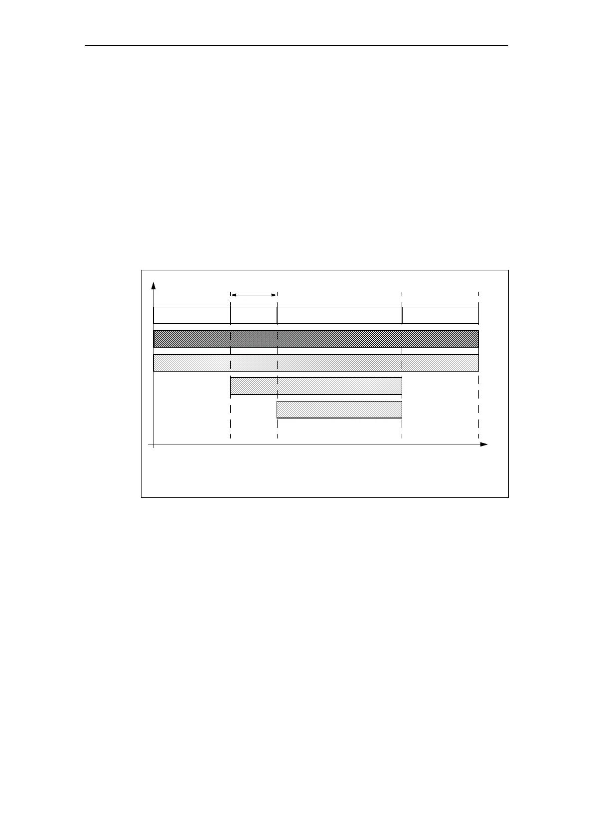
The following display shows a flow chart with the different "activity"
parameters.
Fig. 11-19: Limit monitor activity
OFF Start Motor is running OFF
"ON"
"ON+"
"RUN"
"RUN+"
Class time
Not with TPF
1)
Not with TPF
1)
Not with TPF
1)
Time
Activity
TPF: There is test position feedback, the motor feeder is in the test
position, i.e. its main circuit is isolated from the network. However, the
control voltage is connected.
1)