Logic modules
SIMOCODE pro
GWA 4NEB 631 6050-22 DS 03
11-25
Settings
Note
When using limit monitors, always ensure that the correct range and unit
are used for the analog values connected to the limit input. These always
have a direct influence on the unit of the limit value to be set. The units and
the ranges of all relevant analog values can be found in Chapter B.9 "Data
record 94 - Measured values" and Chapter B.10 "Data record 95 - Service
data/statistical data".
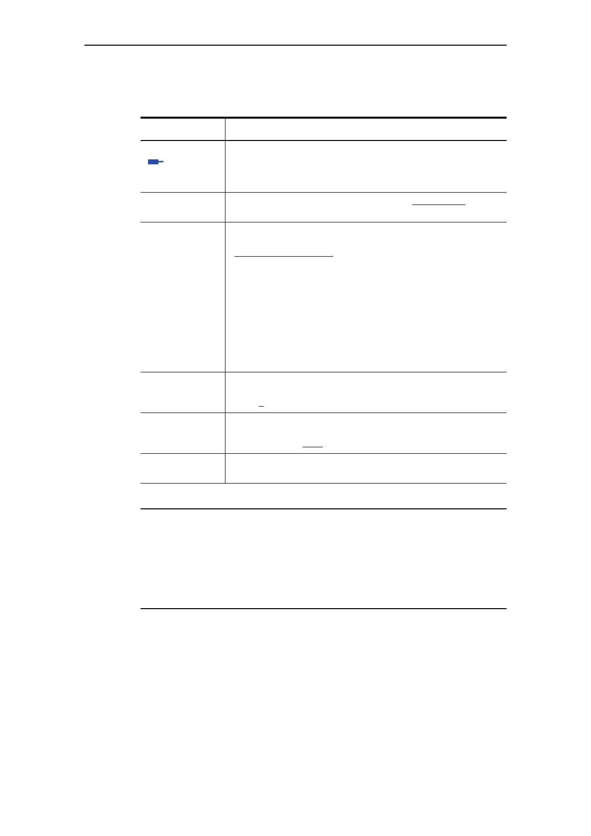
Limit Monitor Description
Input Analog plug of the limit monitor to be connected with the analog
value (2 bytes) which is to be monitored,
e.g. maximum current I_max, cooling down period, actual value of
timers, etc.)
Type Specifies if the limit has to be monitored for overshooting
or
undershooting.
Activity Determines in which motor operating state the limit monitor is to
be evaluated:
• ON, i.e. always evaluate
, independent of whether the motor is
running or not
• ON+, i.e. always evaluate, independent of whether the motor is
running or not
Exception: "TPF", i.e. motor feeder is in the test position
• RUN, i.e. evaluate only if the motor is in the ON state and not in
the test position (TPF)
• RUN+, i.e. evaluate only if the motor is running and the start-up
procedure is finished (i.e. the "Start active" message is no longer
pending) and there is no test position feedback (TPF); Example:
Cos phi monitoring.
Limit Monitor response value. The return value is always determined by
the "Limit monitor - Delay" parameter.
Range: 0
- 65535.
Delay Specifies the time period for which the limit must be constantly
overshot before the "Event - Limit" output is set.
Range: 0 - 25.5 s (0.5 s
).
Marking No parameters. Optional marking for designating the event, e.g.
"Limit>"; Range: Up to 10 characters.
Table 11-13: Limit monitor settings