Mounting, wiring, interfaces
SIMOCODE pro
GWA 4NEB 631 6050-22 DS 03
13-15
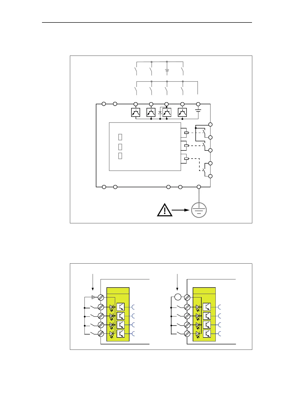
Basic unit connection example
Fig. 13-10: Basic unit connection example
Supplying the inputs of the digital module
• Digital module with 24 V DC input supply
• Digital module with 110 to 240 V AC/DC input supply
Fig. 13-11: Supplying the inputs of the digital module
Device
Bus
Gen. Fault
910 4 5
8
1
2
3
6
7
PROFIBUS DP
SPE/PE
A
B
a)
b)
T1
T2
A1
A2
IN1 IN2
IN3
IN4 24 V
OUT1
OUT2
OUT3
Max. 1.5 MBd
24 V DC external 110 V up to 240 V AC/DC external
Digital module (DM)
DM Inputs
1
2
3
4
IN1
IN2
IN3
IN4
N/M
Digital module (DM)
DM Inputs
1
2
3
4
IN1
IN2
IN3
IN4
N/M
~