EasyManuals Logo
Home>Siemens>Control Unit>SIMOCODE pro

Siemens SIMOCODE pro System Manual

Siemens SIMOCODE pro
694 pages
To Next Page IconTo Next Page
To Previous Page IconTo Previous Page
Page #416 background imageLoading...
Page #416 background image
Mounting, wiring, interfaces
SIMOCODE pro
13-16 GWA 4NEB 631 6050-22 DS 03
Digital module pin assignment
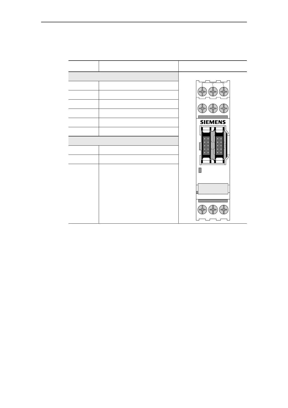
The following table shows the pin assignment of the removable terminals:
Table 13-6: Pin assignment of the removable terminals of the digital module
Connection Assignment
Upper terminals
20 Ground for relay outputs 1 and 2
21 Relay output OUT1
22 Relay output OUT2
23 Digital input IN1
24 Digital input IN2
25 N/M for IN1 to IN4
Lower terminals
26 Digital input IN3
27 Digital input IN4
PE System shielding
20
21
22OUT1
.2
23 24 25IN2
READY
26 27 PEIN3 IN4
IN1

Table of Contents

Other manuals for Siemens SIMOCODE pro

Questions and Answers:

Question and Answer IconNeed help?

Do you have a question about the Siemens SIMOCODE pro and is the answer not in the manual?

Siemens SIMOCODE pro Specifications

General IconGeneral
BrandSiemens
ModelSIMOCODE pro
CategoryControl Unit
LanguageEnglish

Related product manuals