Mounting, wiring, interfaces
SIMOCODE pro
13-26 GWA 4NEB 631 6050-22 DS 03
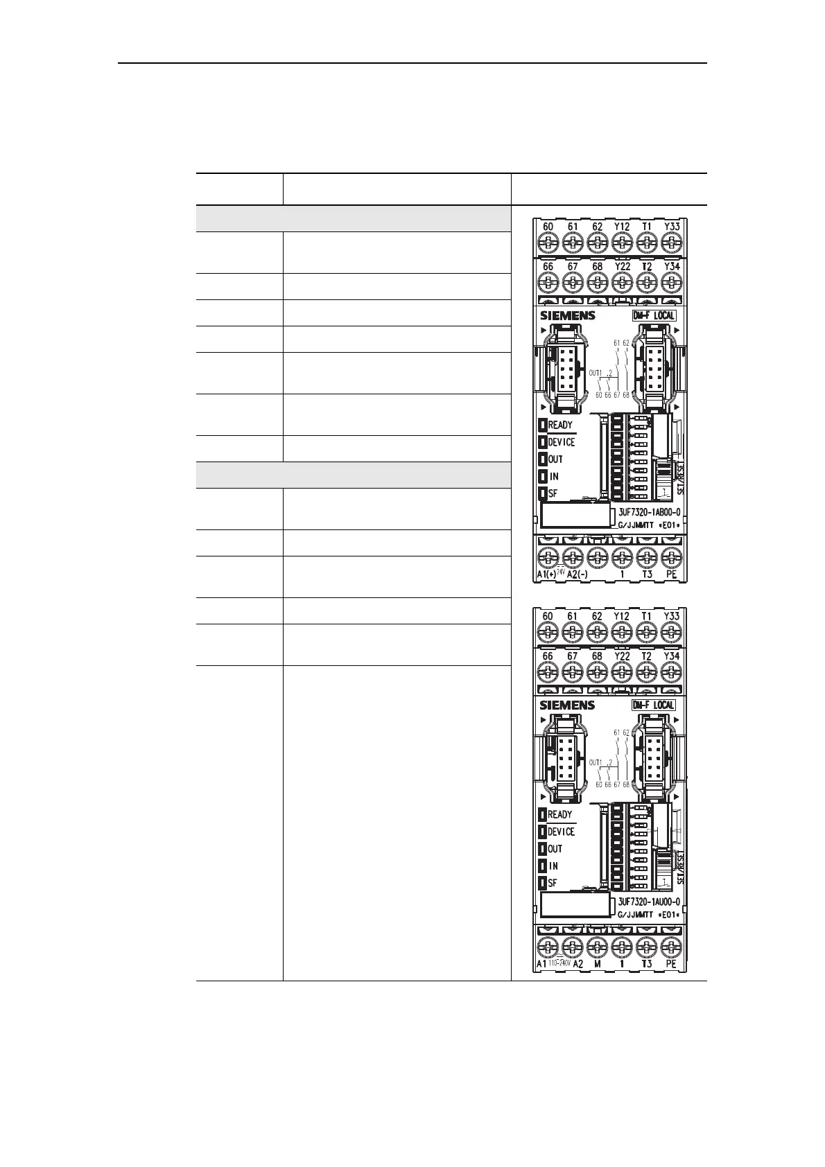
Digital module DM-F Local pin assignment
The following table shows the pin assignment of the removable terminals:
Table 13-11: Pin assignment of the removable terminals of the digital module DM-F Local, 24 V DC
and 110-240 V UC version.
Connection Assignment
Upper terminals
60, 66 Digital module, relay outputs 1 (60)
and 2 (66)
61, 67 Relay enabling circuit 1, NO contact
62, 68 Relay enabling circuit 2, NO contact
Y12, Y22 Sensor input channel 1, channel 2
T1, T2 Supply for sensor inputs
(24 V DC, pulsed)
Y33 Start button (start after rising and
falling edge)
Y34 Feedback circuit
Lower terminals
A1(+) Voltage supply connection 110 to
240 V AC/DC or +24 V DC
A2(-) N or -24 V
M Ground (reference potential sensor
inputs, only 3UF7320-1AU00-0)
1 Cascade input
T3 Supplying the sensor inputs (24 V
DC, static)
PE Protective earth