EasyManuals Logo

Siemens SIMOCODE pro System Manual

Siemens SIMOCODE pro
694 pages
To Next Page IconTo Next Page
To Previous Page IconTo Previous Page
Page #429 background imageLoading...
Page #429 background image
Mounting, wiring, interfaces
SIMOCODE pro
GWA 4NEB 631 6050-22 DS 03
13-29
Digital module DM-F PROFIsafe connection examples
Warning
The protection stipulated must be observed!
This ensures safe tripping in the event of a fault.
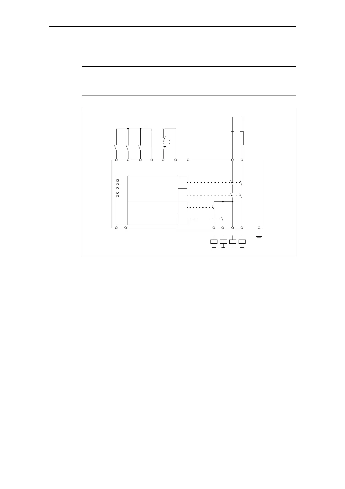
Fig. 13-18: Block diagram DM-F PROFIsafe
Connection examples:
See system manual "Failsafe Digital Modules SIMOCODE pro SAFETY"
-Q1
-Q4
83 85 89 91
90
M
PE
A1 A2
80 86 87 88
Q3
Q4 Q1
Q2
+/L -/N
81 82
Safety logic
Digital module output
READY
DEVICE
OUT
GF
CH1
CH2
OUT1
OUT2
84
(24 V=) (FBC) (T)(IN3)(IN2)(IN1)
DIAZED 4 A, gLgG

Table of Contents

Other manuals for Siemens SIMOCODE pro

Questions and Answers:

Question and Answer IconNeed help?

Do you have a question about the Siemens SIMOCODE pro and is the answer not in the manual?

Siemens SIMOCODE pro Specifications

General IconGeneral
Protection ClassIP20
Mounting TypeDIN rail mounting
Rated Operational Voltage24 V DC
Rated CurrentUp to 820 A
Protection FunctionsOverload, short-circuit, phase failure, asymmetry, ground fault, motor stall
Operating Temperature Range-25°C to +60°C
Communication ProtocolsPROFIBUS DP, PROFINET, Modbus RTU
Analog OutputsUp to 2
Temperature MonitoringPTC/KTY, RTD (PT100/PT1000)
Digital OutputsRelay outputs, Solid-state outputs
Analog Inputs0/4-20mA, PT100/PT1000

Related product manuals