EasyManuals Logo

Siemens SIMOCODE pro System Manual

Siemens SIMOCODE pro
694 pages
To Next Page IconTo Next Page
To Previous Page IconTo Previous Page
Page #428 background imageLoading...
Page #428 background image
Mounting, wiring, interfaces
SIMOCODE pro
13-28 GWA 4NEB 631 6050-22 DS 03
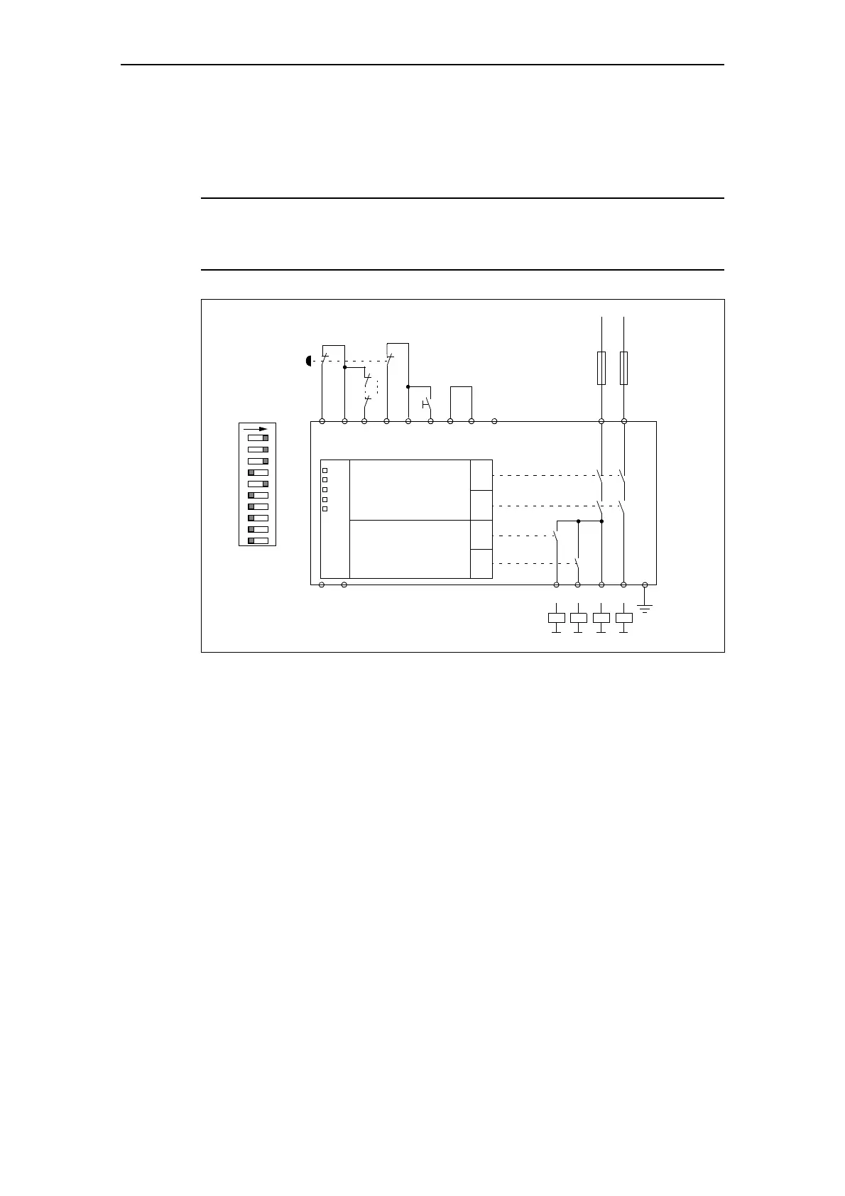
Digital module DM-F Local connection example
DM-F Local with cross circuit detection, 2 NCs, 2 channels,
monitored start.
Warning
The protection stipulated must be observed!
This ensures safe tripping in the event of a fault.
Fig. 13-17: Connection example "DM-F Local with cross circuit detection, 2 NCs, 2 channels,
monitored start"
Further connection examples:
See system manual "Failsafe Digital Modules SIMOCODE pro SAFETY"
-Q4
-Q1
START
Y22 T2 Y34 Y12 T1 Y33 T3 1 M
A1 A2
61
62
60 66 67 68
Q4 Q2 Q1
Safety logic
READY
DEVICE
OUT
IN
GF
CH1
CH2
+/L -/N
OUT1
OUT2
Digital module output
Q3
DIAZED 4 A, gLgG
PE
ON
21 345678910

Table of Contents

Other manuals for Siemens SIMOCODE pro

Questions and Answers:

Question and Answer IconNeed help?

Do you have a question about the Siemens SIMOCODE pro and is the answer not in the manual?

Siemens SIMOCODE pro Specifications

General IconGeneral
Protection ClassIP20
Mounting TypeDIN rail mounting
Rated Operational Voltage24 V DC
Rated CurrentUp to 820 A
Protection FunctionsOverload, short-circuit, phase failure, asymmetry, ground fault, motor stall
Operating Temperature Range-25°C to +60°C
Communication ProtocolsPROFIBUS DP, PROFINET, Modbus RTU
Analog OutputsUp to 2
Temperature MonitoringPTC/KTY, RTD (PT100/PT1000)
Digital OutputsRelay outputs, Solid-state outputs
Analog Inputs0/4-20mA, PT100/PT1000

Related product manuals