DC link components
7.1 Control Supply Module CSM
SINAMICS S120 Combi
Manual, 11/2017, 6SL3097-4AV00-0BP7
157
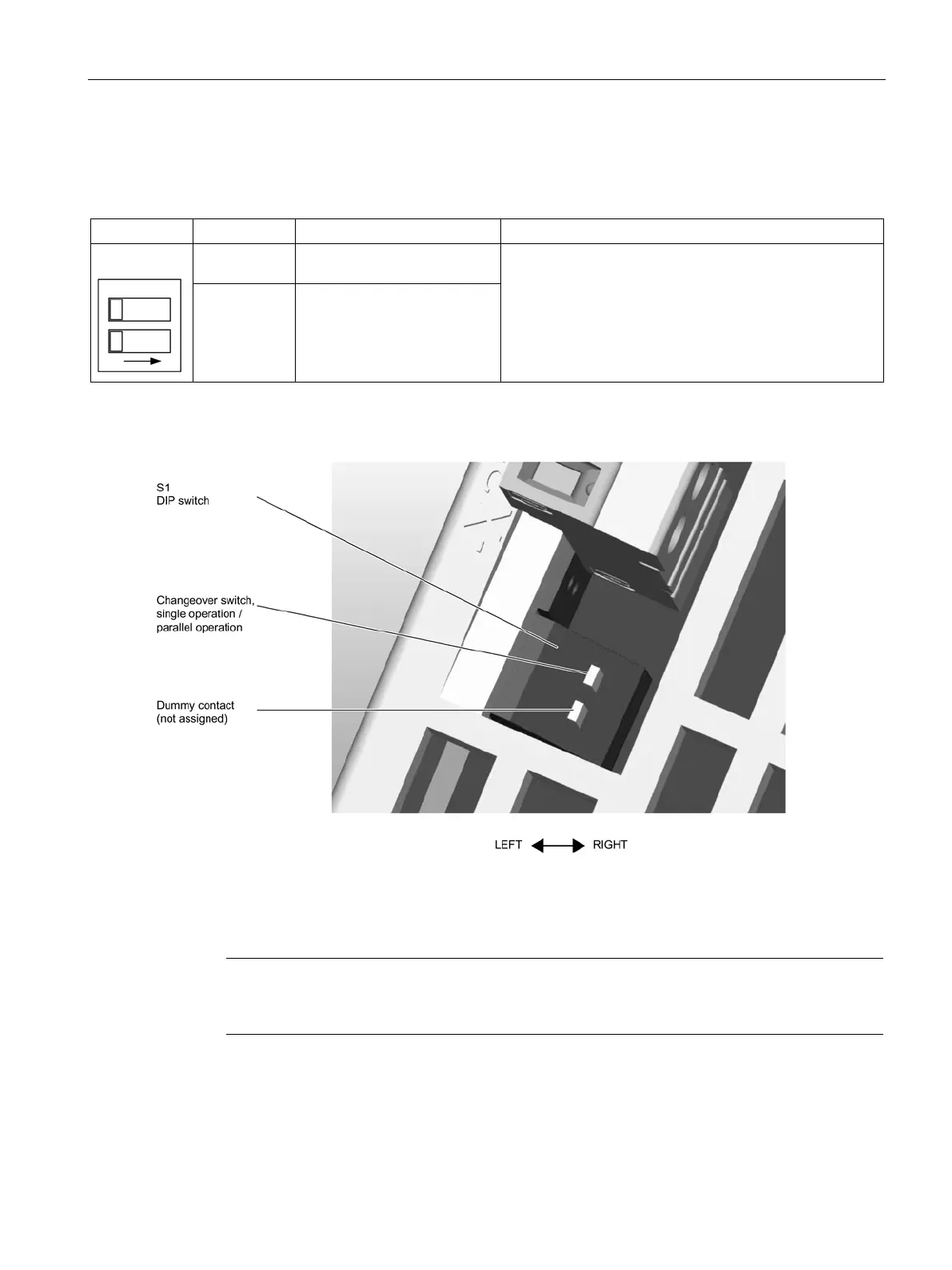
Table 7- 4 DIP switch S1
1 Changeover switch, single
operation / parallel operation
Left: Single operation
Right: Parallel operation
Changing over the output characteristic
2 Dummy contact
(not used)
It is only permissible to changeover when in the no-voltage state.
Figure 7-2 DIP switch on the upper side of the component
When delivered, "single operation" is set. Both switches are set to the left.
Note
The DIP switch must be set to "single operation" when operating the Control Supply Module
on the S120 Combi.

 Loading...


