S120 Combi Power Modules
4.5 Meaning of the LEDs on the S120 Combi
SINAMICS S120 Combi
Manual, 11/2017, 6SL3097-4AV00-0BP7
85
Motor holding brake for servo 2 and servo 3 (parameterizable in the expert list)
● Settings in the Expert list
– Servo2-p1215=3 and Servo3-p1215=3
(3: Motor holding brake as for the sequence control, connection via BICO, no SBC
possible)
● BiCo connections from the sequence control to digital outputs on the Control Unit
– BICO interconnection to "open servo holding brake"
• BiCo in CU_I-p0744: Servo2-r0899.12
• BiCo in CU_I-p0745: Servo3-r0899.12
– Output definition in CU_I
• CU_I-p0728.14 =1
• CU_I-p0728.15 =1
Note
The circuit shown above is only an example.
A wiring diagram of the digital inputs/outputs on the PPU can be found in the SINUMERIK
828D Manual PPU, Edition 03/201
3.
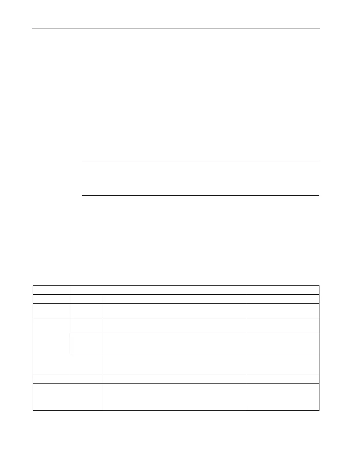
Meaning of the LEDs on the S120 Combi
The SINAMICS S120 Combi has 2 LEDs to display the status. The LED statuses for the
S120 Combi are described in the table below. The status display refers to the internal infeed,
the spindle and the servo drives and the TTL encoder evaluation of the S120 Combi Power
Module
Table 4- 17 Meaning of the LEDs on the S120 Combi
Off Off The electronics power supply is missing or outside the per-
missible tolerance range.
Connect and check the elec-
Green Off The component is ready for operation. Cyclic DRIVE-CLiQ
communication is taking place.
-
Orange The component is ready for operation. Cyclic DRIVE-CLiQ
communication is taking place.
The DC-link voltage is present.
-
Red The component is ready for operation. Cyclic DRIVE-CLiQ
communication is taking place.
The DC-link voltage is too high.
Check the line supply volt-
age.
DRIVE-CLiQ communication is being established.
Red - This component has at least one fault.
The LED is activated irrespective of whether the correspond-
ing messages have been reconfigured.
Remedy and acknowledge
fault

 Loading...


