Additional system components
9.1 Terminal Module TM54F
SINAMICS S120 Combi
208 Manual, 11/2017, 6SL3097-4AV00-0BP7
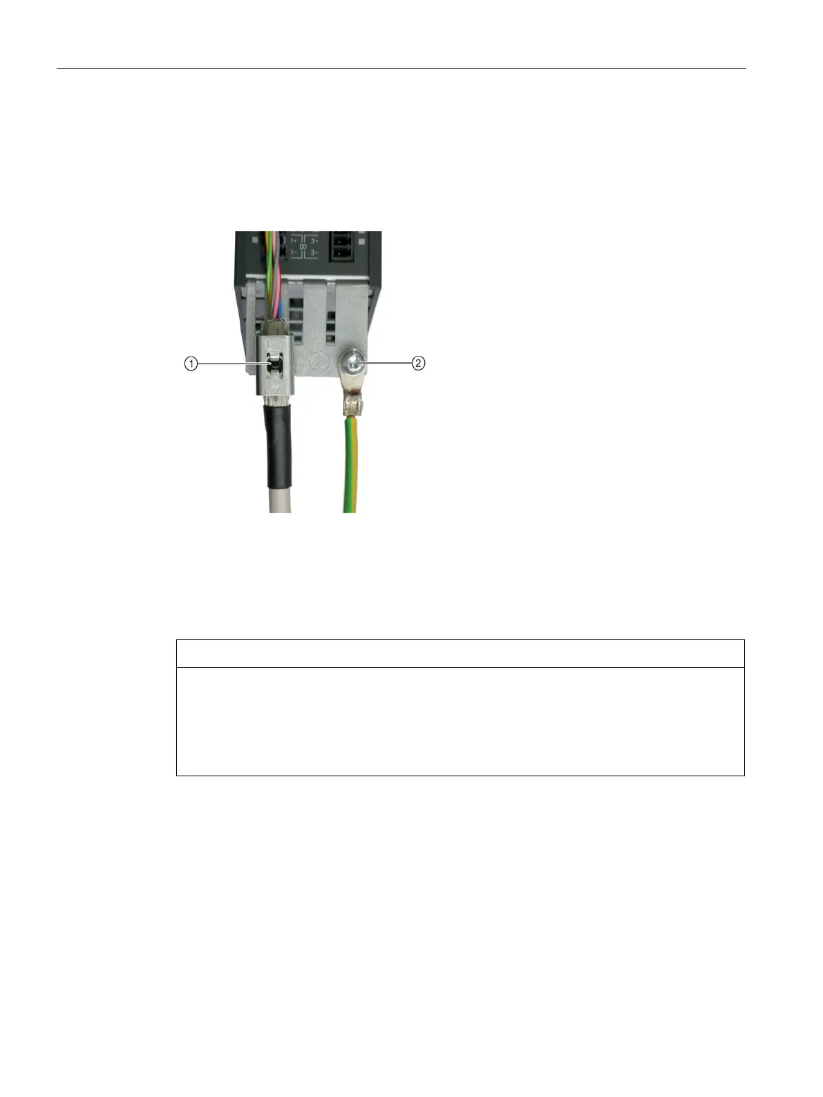
Protective conductor connection and shield support
It is always advisable to shield the digital input and output wiring.
The following diagram shows a typical Weidmüller shield connection clamp for the shield
support.
Shield connection terminal, Weidmüller company, type: KLBUE CO1, Article number:
Protective conductor connection M4 / 1.8 Nm
Figure 9-5 Protective conductor connection and shield support
Damage or faulty operation due to incorrect shielding or inadmissible cable lengths
If the correct shielding procedures or the permissible cable lengths are not observed, it can
cause damage or the machine may malfunction.
• Only use shielded cables.
• Do not exceed the cable lengths stated in the technical data.

 Loading...


