Additional system components
9.1 Terminal Module TM54F
SINAMICS S120 Combi
192 Manual, 11/2017, 6SL3097-4AV00-0BP7
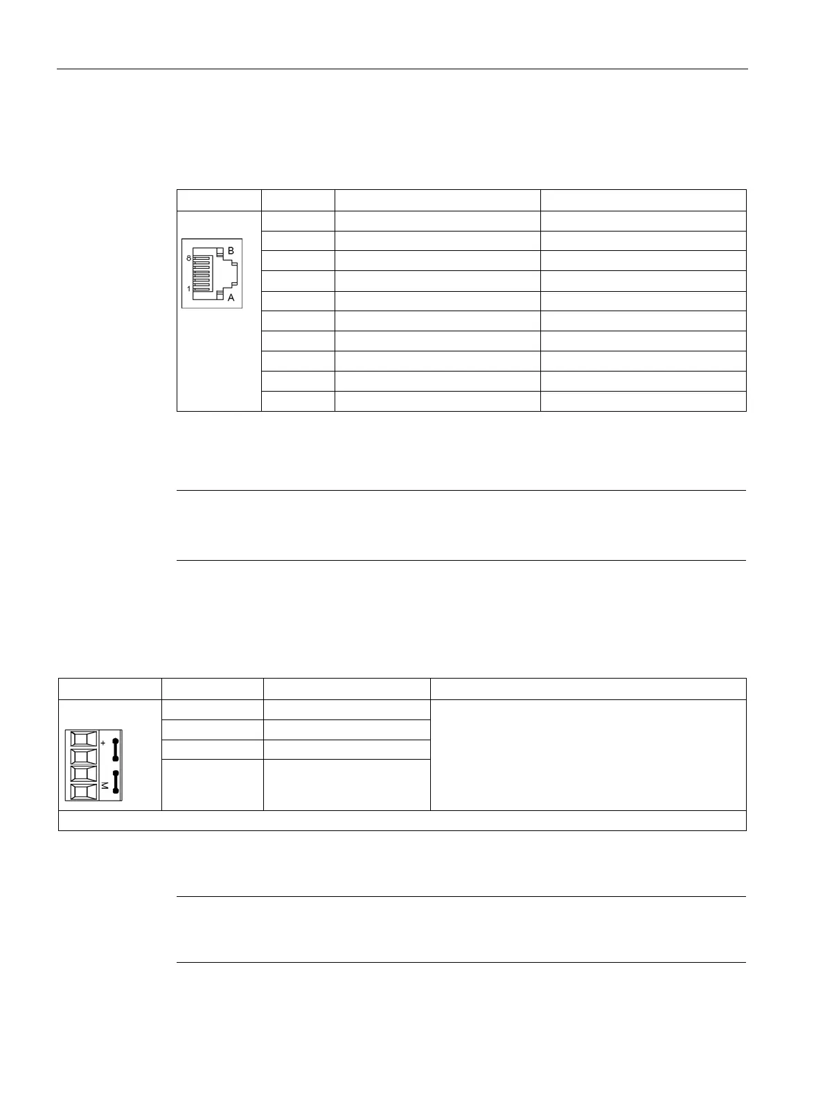
X500/X501 DRIVE-CLiQ interfaces
Table 9- 2 X500/X501: DRIVE-CLiQ interfaces
4 Reserved, do not use
The blanking covers for the DRIVE
-CLiQ interfaces are included in the scope of delivery.
Blanking covers (50 x) Article number: 6SL3066-4CA00-0AA0
Note
Maximum cable length
The maximum DRIVE
-CLiQ cable length is 100 m.
X514 power supply for digital outputs and sensors
Table 9- 3 X514: Power supply
Voltage: 24 VDC (20.4 ... 28.8 V)
Current consumption: Maximum 4 A
1)
Maximum current through the jumper in the connector:
20 A (15 A according to UL/CSA)
M1 Electronics ground
M1 Electronics ground
Type: Screw terminal 3 (Page 288)
1)
Including the current consumption for the digital outputs and to supply the sensor
The maximum cable length that can be connected is 30 m.
Note
The two "+" and "M1" terminals are jumpered in th
e connector. This ensures that the supply
voltage is looped through.

 Loading...


