S120 Combi Power Modules
4.3 Interface description
SINAMICS S120 Combi
Manual, 11/2017, 6SL3097-4AV00-0BP7
79
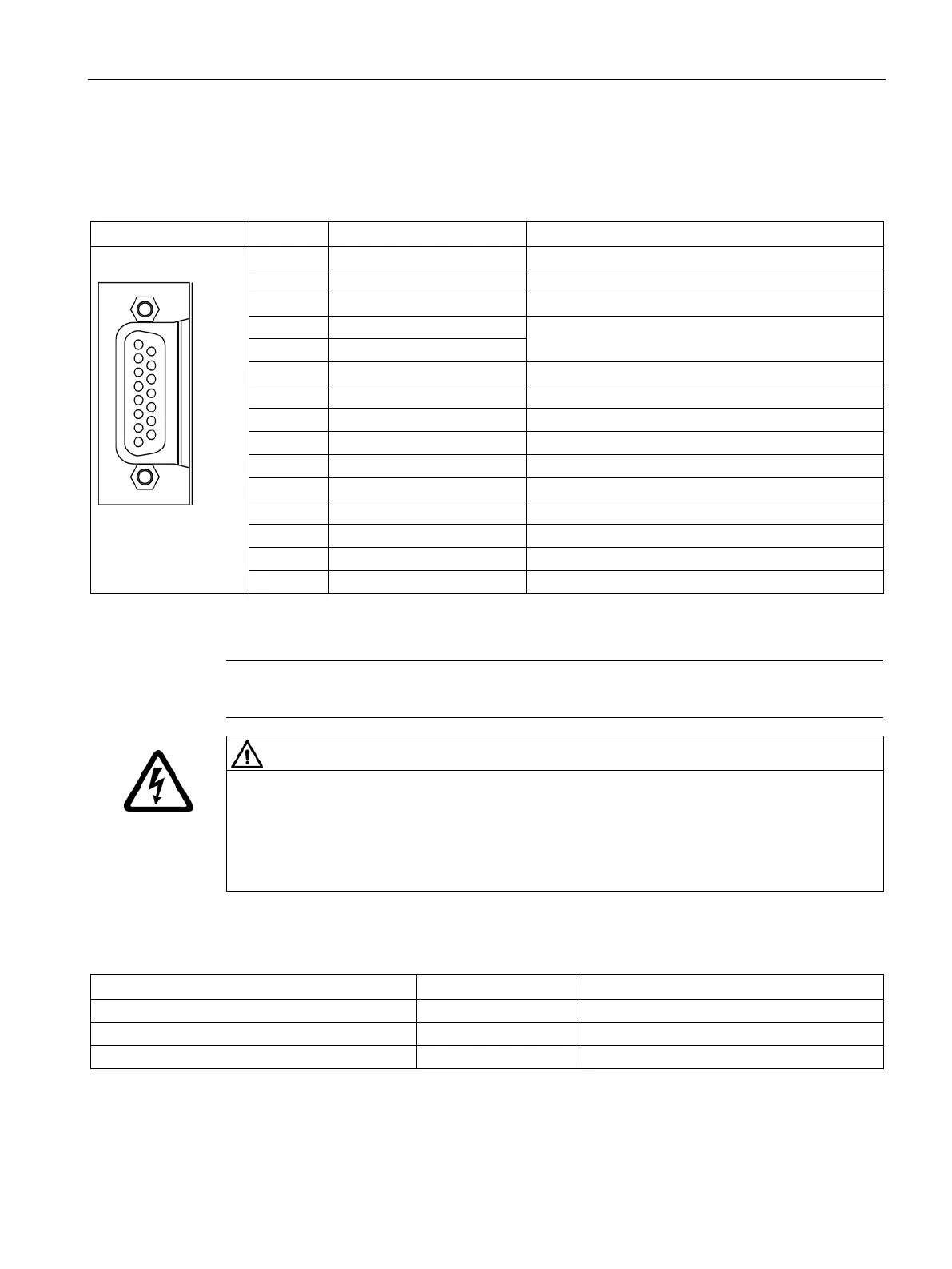
Table 4- 13 Encoder interface X220
Temperature sensor KTY84-1C130 / PT1000 / PTC
2 Clock Clock
Encoder power supply
Sense input of encoder power supply
Ground for encoder power supply
Temperature sensor KTY84-1C130 / PT1000 / PTC
Inverse reference signal R
Inverse incremental signal B
Inverse incremental signal A
Type: Sub-D socket, 15-pin; TTL encoder; max. cable length 100 m
V TTL encoders are supported.
Electric shock in the event of voltage flashovers at the temperature sensor
Voltage flashovers to the signal electronics can occur in motors without safe electrical
separation of the temperature sensors.
• Use temperature sensors that comply with the specifications relating to safe electrical
separation.
Table 4- 14 Technical data of the encoder system supply
DC
5 (with or without remote sense)
1)
Encoder frequency that can be evaluated (f
encoder
A controller compares the encoder system supply voltage - sensed via the remote sense cables - with the reference
supply voltage of the encoder system, and adjusts the supply voltage for the encoder system at the output of the drive
module until the required supply voltage is obtained directly at the encoder system.

 Loading...


