Encoder system connection
10.1 Sensor Module Cabinet-Mounted SMC20
SINAMICS S120 Combi
Manual, 11/2017, 6SL3097-4AV00-0BP7
233
Table 10- 5 Technical data
Voltage
Current (without encoder system)
Current (with encoder system)
V
DC
A
DC
A
DC
24 (20.4 … 28.8)
≤ 0.20
≤ 0.35
Encoder system power supply
Voltage
V
DC
5 (with remote sense)
1)
Encoder frequency that can be evaluated (f
encoder
2)
3)
Maximum encoder cable length
At the housing with M4 / 1.8 Nm screw
A controller compares the encoder system supply voltage - sensed via the remote sense cables - with the reference
supply voltage of the encoder system, and a
djusts the supply voltage for the encoder system at the output of the sensor
module until the required supply voltage is obtained directly at the encoder system.
Only possible for SSI encoders with 5 V supply.
3)
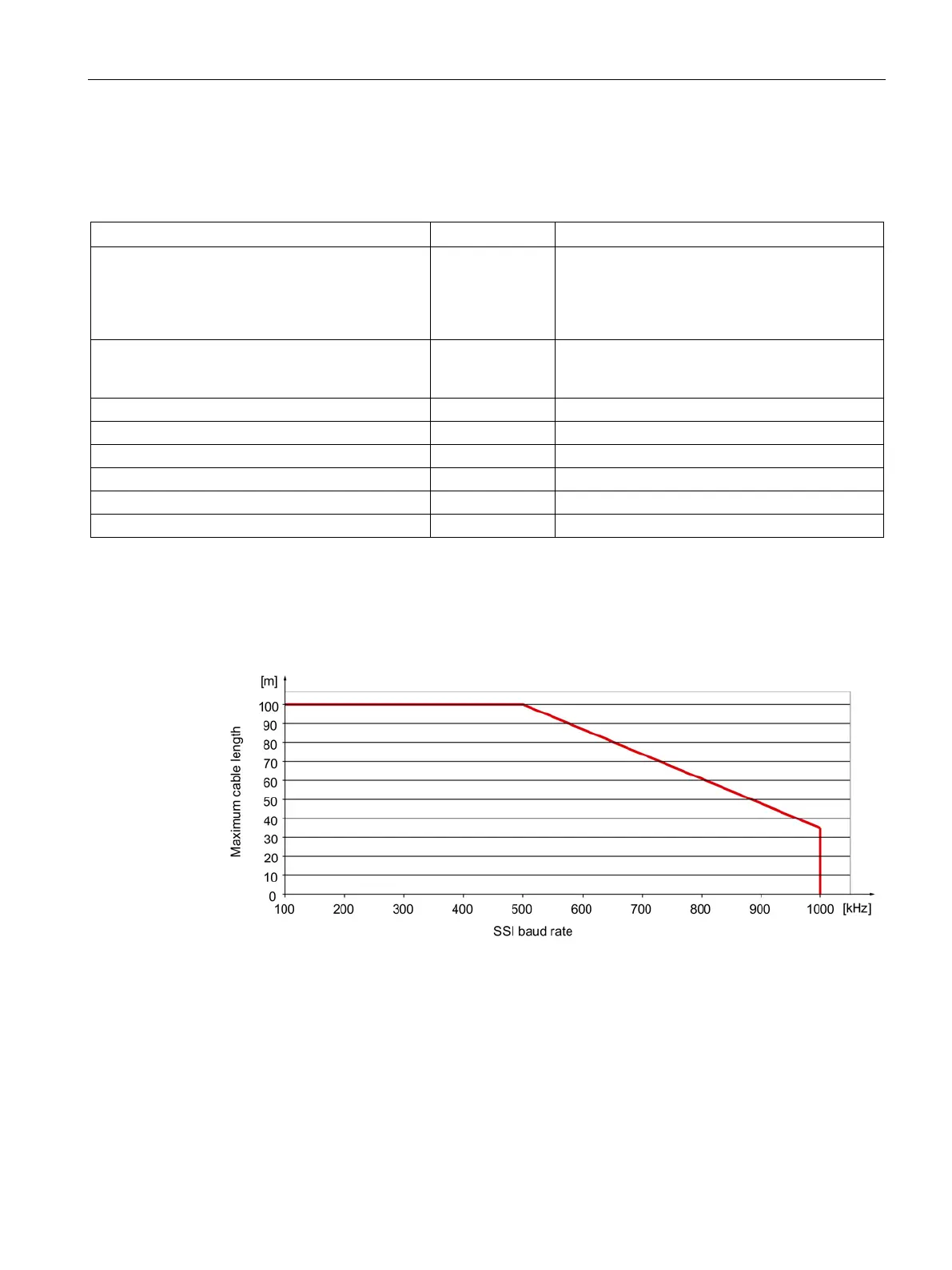
See the diagram "Maximum cable length depending on the SSI baud rate for SSI encoders"
Figure 10-4 Maximum cable length depending on the SSI baud rate for SSI encoders

 Loading...


