Cabinet design and EMC
12.8 Note on control cabinet cooling
SINAMICS S120 Combi
302 Manual, 11/2017, 6SL3097-4AV00-0BP7
Electronics losses of power units
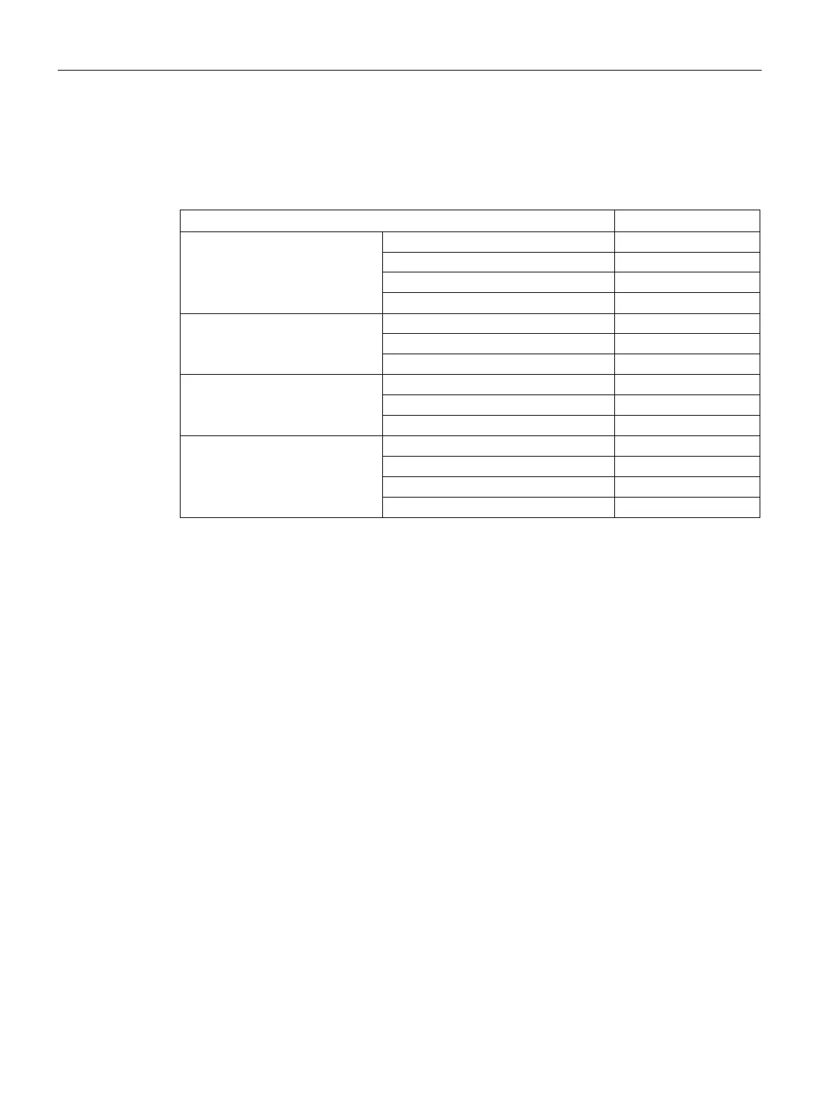
Table 12- 20 Electronics losses for Motor Modules Booksize Compact and S120 Combi Power Mod-
ules
Single Motor Module
18 A 20.4
Double Motor Module
3 A 27.6
S120 Combi
3 axes Power Module
1)
S120 Combi
4 axes Power Module
1)
10 kW / 24 A / 12 A / 12 A / 12 A
16 kW / 18 A / 9 A / 5 A / 5 A
16 kW / 24 A / 9 A / 9 A / 9 A
20 kW / 30 A / 12 A / 9 A / 9 A
1)
Without power loss of the external fan
Losses in partial-load operation
Losses in the partial-load range for the S120 Combi
The losses of the S120 Combi in partial-load operation can be calculated using the following
formula:
P
V
= a + b + IN1 * P1 + S1 * I1 + S2 * I2 + S3 * I3 + S4 * I4
a: Electronics losses of the S120 Combi
b: Electronics losses of the external fan unit (article number: 6SL3161-0EP00-0AA0)
IN1, S1 - S4: Coefficients to calculate the power loss
P1: Infeed power [kW] (LINE X1)
I1: Spindle current [A] (SPINDLE X2)
I2: Current of the 1st feed axis (servo X3)
I3: Current of the 2nd feed axis (servo X4)
I4: Current of the 3rd feed axis (servo X5)

 Loading...


