Additional system components
9.1 Terminal Module TM54F
SINAMICS S120 Combi
196 Manual, 11/2017, 6SL3097-4AV00-0BP7
X523 fail-safe digital output
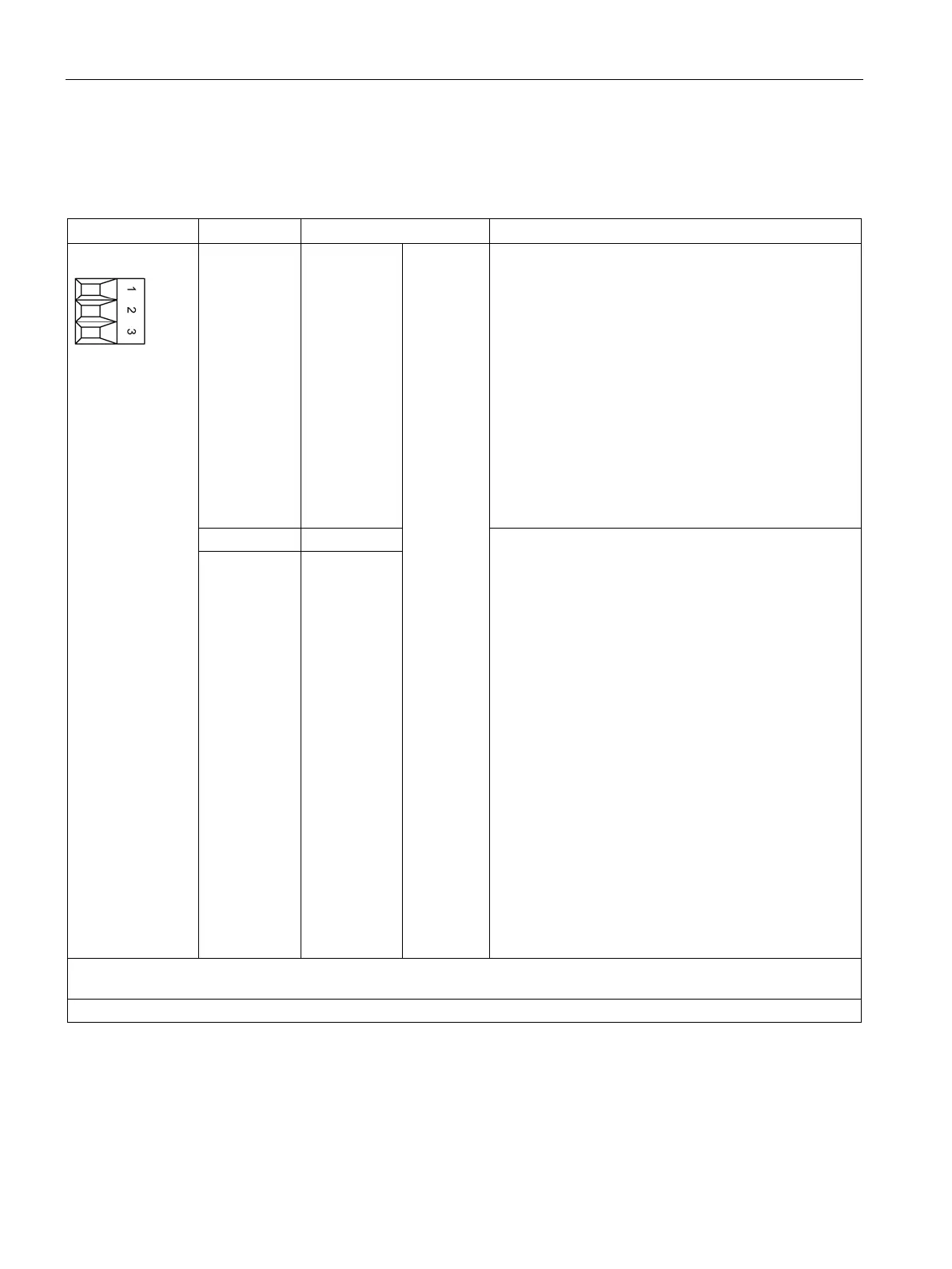
Table 9- 7 X523: Fail-safe digital output
1 DI 20
F-DO 0
Voltage: -3 … +30 VDC
Electrical isolation: Yes
Reference potential: M1
Input characteristic acc. to IEC 61131-2, type 1
Input voltage (including ripple)
"1" signal: 15 … 30 V
"0" signal: -3 … +5 V
Input current
at 24 VDC: Typical 3.2 mA
for "1" signal: > 0.5 mA
Input delay:
2)
for "0" → "1": Typical 30 μs
for "1" → "0": Typical 60 μs
Switching frequency: Maximum 100 Hz
Voltage: 24 VDC
Electrical isolation: Yes
Reference potential
M1 for DO 0+
Terminal L1+, L2+ or L3+ for DO 0-
Output voltage
"1" signal, with load: > X514.+ -2 V
Output current
For each output: ≤ 0.5 A
Sum of all 4 outputs: ≤ 2 A
Residual current for "0" signal: < 0.5 mA
Short-circuit protection, automatic restart after a short-
circuit
Load types: ohmic, capacitive, inductive
Output delay
2)
for "0" → "1": 300 μs (ohmic load)
for "1" → "0": 350 μs (ohmic load)
Switching frequency
for ohmic load: Maximum 100 Hz
for inductive load: Maximum 0.5 Hz
for lamp load: Maximum 10 Hz
3 DO 0-
An F-DO comprises 2 digital outputs and 1 digital input for feedback signal
F-DO 0 = terminals 1, 2, and 3
Type: Screw terminal 1 (Page 288)
DI: digital input; DO: digital output F-DO: Fail-safe digital output

 Loading...


