S120 Combi Power Modules
4.3 Interface description
SINAMICS S120 Combi
Manual, 11/2017, 6SL3097-4AV00-0BP7
75
Note
Customer-specific implementation of forced ventilation
If you implement the forced ventilation of the SINAMICS S120 Combi devices at the
customer, terminals 1 and 2 must be jumpered at X12 and X13 in order to prevent the
occurrence of a fan error message.
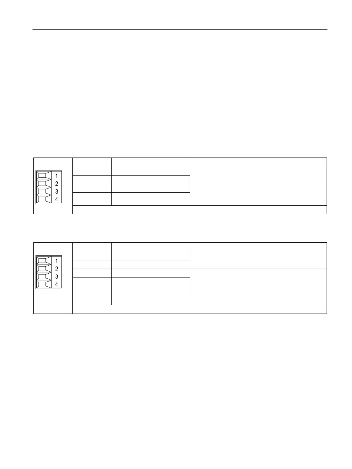
Table 4- 10 X21 EP terminals - infeed
Reserved, do not use
Supply voltage: 24 VDC (20.4 ... 28.8 V)
Current consumption, typical: 4 mA at 24 V
4 EP M1 (Enable Pulses)
Type: Screw terminal 1 (Page 288)
Table 4- 11 X22 EP terminal/temperature sensor - axes
Temperature sensors
1)
: KTY84–1C130 / PT1000 / PTC /
bimetallic switch with NC contact
Supply voltage: 24 VDC (20.4 ... 28.8 V)
Current consumption, typical: 4 mA at 24 V
Isolated input
The pulse inhibit function is only available when Safety
Integrated Basic Functions are enabled.
4 EP M1 (Enable Pulses)
Type: Screw terminal 1 (Page 288)
1)
The temperature sensor type can be selected by parameter (see the SINAMICS S120/S150 List Manual).

 Loading...


