Cabinet design and EMC
12.4 24 V DC supply
SINAMICS S120 Combi
280 Manual, 11/2017, 6SL3097-4AV00-0BP7
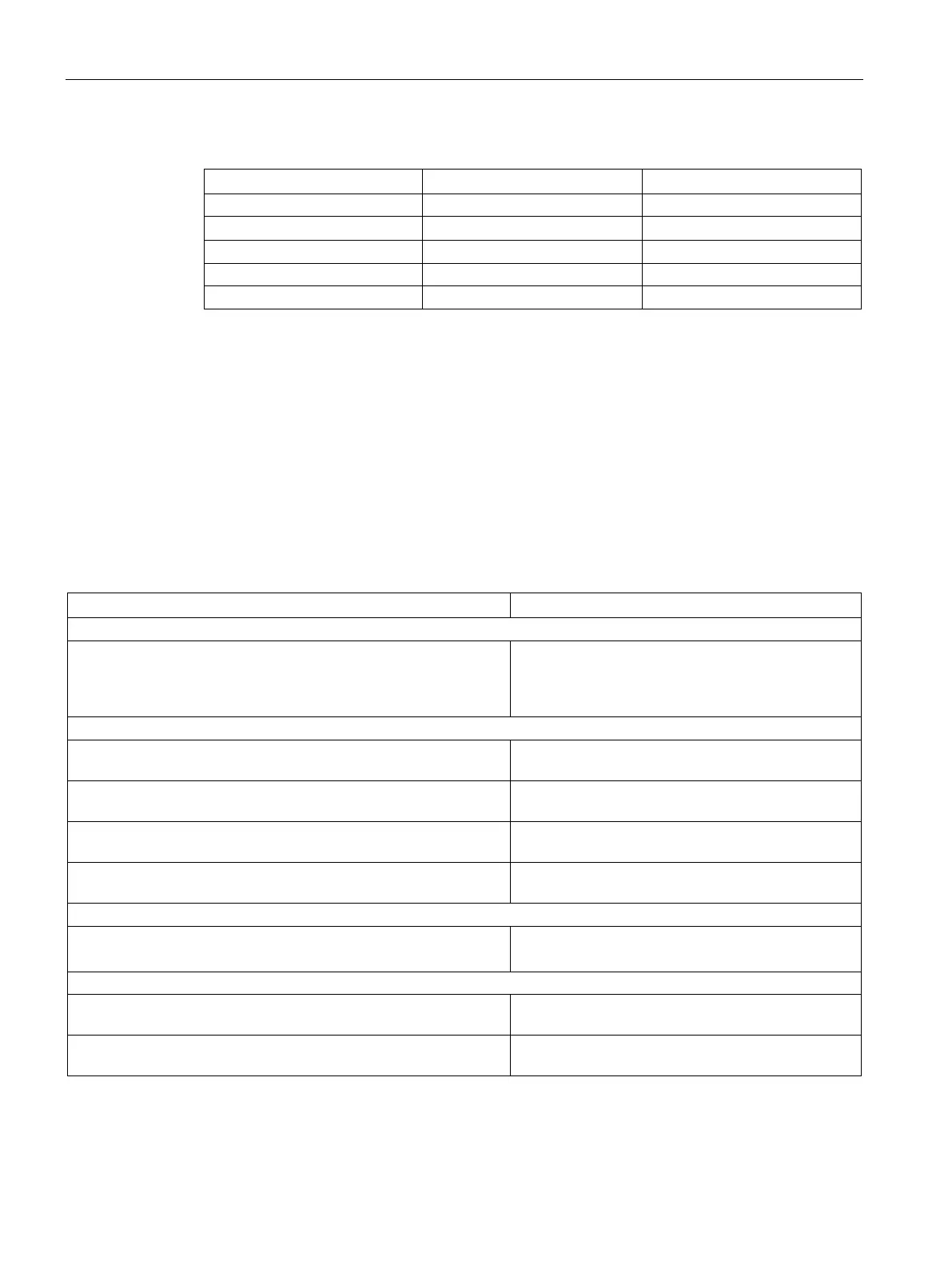
Table 12- 1 MCBs by core cross-section and temperature
2
2.5 mm
2
16 A 10 A
2
6 mm
2
32 A 20 A
The tripping characteristic of the miniature circuit breakers must be selected to match the
loads to be protected and the maximum current provided by the supply unit in the event of a
short circuit.
Typical 24 V current consumption of the components
A separate 24 V power supply must be used for the SINAMICS S120 drive group.
The following table can be used to calculate the 24 V DC power supply. The values for
typical current consumption are used as a basis for configuration.
Table 12- 2 Overview of 24 V DC current consumption
Typical current consumption [A
DC
]
SINUMERIK 828D - PPU without load
SINUMERIK 828D - PPU with full load (USB, handwheel, ...)
SINUMERIK NCU 710.3 PN without load
SINUMERIK NCU 710.3 PN with full load
1.2
2.5
0.9
SMC20
without/with encoder system
SMC30
without/with encoder system
SME20
without/with encoder system
SME25
without/with encoder system
TM54F (without digital outputs, without DRIVE-CLiQ)
Per digital output/DRIVE-CLiQ
0.2
Additional system components
DMC20 (without DRIVE-CLiQ)
0.15
DME20 (without DRIVE-CLiQ)
0.15

 Loading...


